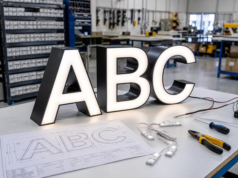

A channel letter sign rarely fails in a completely random way. When one small area goes dark, one whole letter disappears, or several neighbouring letters stop illuminating at the same time, the pattern itself provides useful information. A partial outage usually means that some part of the electrical system is still operating, so the fault can often be narrowed to a smaller group of LED modules, a wiring connection, an individual circuit branch, a power supply, a controller, or an environmental problem such as moisture.
When only part of a channel letter sign stops working, common causes include failed LED modules, loose or corroded connectors, damaged low-voltage wiring, a failing or overloaded power supply, voltage drop, water intrusion, or a problem affecting one electrical branch. The exact shape and location of the dark area are often the most useful clues for deciding which part of the system should be inspected first.
Consider a storefront where seven letters remain evenly illuminated but the final half of one letter suddenly turns black. Replacing the entire sign would make little sense, and replacing a power supply without checking the affected circuit could waste both time and parts. Experienced sign technicians begin with a simpler question: where does normal illumination stop, and what electrical component is shared by everything beyond that point? Reading the failure pattern correctly can make troubleshooting much faster and prevent unnecessary replacement.
What Does a Partial Channel Letter Failure Mean?

A partial channel letter failure means some parts of the sign are still receiving usable electrical power while another section is no longer producing normal light. The size, position, and behaviour of the dark area help distinguish a local LED problem from a failed connector, individual letter feed, circuit branch, power supply, controller, voltage-drop problem, or environmental fault.
Is One LED Section Dark?
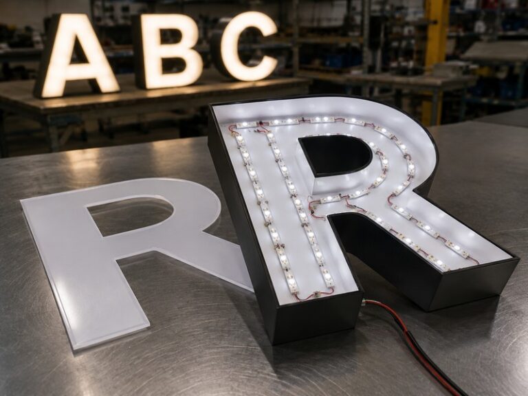
When only a small area within one letter goes dark while the remaining face stays evenly illuminated, the problem is usually more local than a complete electrical-system failure. A channel letter commonly contains several LED modules rather than one continuous lamp. The letter can also contain a face, return, back panel, wiring, wire exit, mounting features, and weather-protection details, allowing a small section to fail independently while the rest continues operating.
A failed LED module is an obvious possibility, but it is not the only explanation. A perfectly functional module remains dark when its positive or negative conductor is disconnected, when an upstream connector has opened, or when a corroded joint creates enough resistance to interrupt the circuit. For that reason, experienced technicians do not normally replace the first dark module they see without first checking whether the expected low-voltage supply reaches that module or module group.
The visual boundary between bright and dark areas is especially useful. If several modules operate normally and every module after one connection point is dark, the fault may follow the wiring path rather than the physical shape of the letter. If one isolated area is darker while illumination is normal around it, a single module, its local connection, or even its physical position becomes more likely. A detached module can still produce light while pointing away from the face, creating an apparent dark spot without being electrically dead.
Is One Letter Completely Dark?
One complete letter going dark while neighbouring letters remain normally illuminated creates a different diagnostic pattern. Because other letters are still working, the building supply has not necessarily disappeared and the entire sign does not need to be treated as one failed electrical unit. Attention should move toward the components shared by everything inside the dark letter, including its low-voltage feed, branch connection, wiring, wire exit, splice, or circuit assignment.
Channel letters are normally built as identifiable dimensional units and then positioned together according to the approved layout. This construction is one reason an electrical problem can remain limited to a single letter. The dark letter may have a dedicated branch, may share a supply with only part of the sign, or may depend on a specific connection inside a raceway or behind the mounting surface.
The original wiring arrangement becomes extremely valuable during service. If the installer can identify exactly which circuit feeds the dark letter, the investigation can begin at the relevant branch rather than by opening every letter in the sign. Where drawings are unavailable, technicians should document the wiring as they trace it. That information can significantly reduce service time if another problem occurs later.
Are Several Letters Dim or Intermittent?
Several letters failing, dimming, or flickering together usually shifts attention away from isolated LED-module faults and toward a component shared by the affected group. Multiple letters may use the same power supply, low-voltage branch, raceway junction, connector, controller channel, or cable route. A single problem at that shared point can therefore produce a visible failure covering several letters while the remaining sign continues to work normally.
Intermittent behaviour adds another useful clue. If the affected letters illuminate normally when first switched on but begin flickering or shutting down after prolonged operation, temperature, supply loading, or a marginal connection may deserve greater attention. If the same group behaves differently after heavy rain, moisture and connector protection become more important possibilities. If distant letters remain illuminated but appear consistently dimmer than letters closer to the supply, wire length, current and voltage drop should be evaluated.
The most useful service record is therefore more specific than saying that “part of the sign is not working.” Record which letters are affected, whether they are fully dark or merely dim, whether the problem is permanent or intermittent, and whether weather, operating time, recent installation work, or previous repairs change the symptom. Those details often narrow the diagnostic path before a letter is opened.
| Visible Symptom | First Area to Investigate | Useful Diagnostic Clue |
| One small dark section | LED module or nearby connection | Other modules in the same letter remain normal |
| Half of one letter dark | Internal branch or splice | Clear bright-to-dark transition |
| One complete letter dark | Letter feed or branch | Neighbouring letters continue working |
| Several letters dark | Shared supply or circuit | Failed letters match an electrical group |
| Distant letters appear dim | Voltage distribution | Brightness decreases with wiring distance |
| One RGB colour disappears | Controller or colour channel | Other colours may still operate |
| Entire sign is dark | Common upstream system | No illuminated group remains |
Which Parts Can Cause the Failure?

A partial outage does not have one universal cause because a channel letter lighting system contains several components that depend on one another. LED modules, wires, connectors, power supplies, branch circuits, and sometimes dimmers or RGB/RGBW controllers can each create a localized fault. The most reliable diagnosis identifies which component is common to the failed area instead of replacing parts randomly.
Can an LED Module Fail?
Individual LED modules can fail while every other module in the sign continues operating. In a large channel letter containing many modules, one defective unit may produce only a relatively small dark area on the face, while several neighbouring module failures can create a larger visible shadow. This is one reason a localized outage often looks very different from the clean boundary created by an entire failed circuit.
A dark module should still be tested before being condemned. A module with no supply voltage is behaving exactly as expected, even though it appears identical to a failed module from outside the letter. Technicians therefore need to distinguish component failure from supply failure. Polarity, connector condition, conductor continuity, upstream splices, and the actual voltage at the affected point all matter when confirming the cause.
Manufacturing inspection should reflect the same logic. The documented iduoduo Channel Letter process includes checks of module type, LED quantity, module attachment, circuit grouping, wiring, polarity, connectors, insulation, and power supply rather than treating successful illumination as the only electrical quality criterion. This approach matters because a sign that turns on once can still contain a poorly secured connection or routing problem that becomes visible later.
Physical placement can also imitate electrical failure. If a module becomes detached and points sideways rather than toward the illuminated face, the face can develop a dark zone even while the module continues producing light. Checking both the electrical condition and the physical LED layout prevents technicians from replacing a working component when the real problem is mechanical positioning.
Can a Connector or Wire Fail?
A connector may be physically small, but the area affected by its failure can be surprisingly large. Low-voltage channel letter systems can include module leads, extension wires, branch connections, power-supply outputs, raceway junctions, wall penetrations, and field splices. Each electrical transition must remain mechanically secure and electrically reliable throughout installation, temperature cycling, vibration, weather exposure, and future maintenance.
Loose connections often begin as intermittent problems rather than immediate permanent outages. A sign may flicker when the wind moves a cable, fail only after heating, or recover temporarily after switching off. Outdoor connections may deteriorate more gradually when water or condensation reaches exposed metal. Corrosion increases resistance and can eventually create enough voltage loss or instability to affect one module group or an entire branch.
Wiring can also be damaged mechanically. Conductors may become trapped behind letters during installation, insulation can rub against sharp metal edges, and wires can be pulled when a face or back is opened for maintenance. In these situations, the original LED modules and power supply may still be perfectly functional.
Good production and installation practice therefore includes deliberate wire routing, consistent polarity identification, protected connections, sufficient strain relief where appropriate, and service access. A neat wiring layout is not merely cosmetic. Years later, it allows a technician to follow the electrical path logically rather than guessing which hidden conductor feeds the dark area.
Can the Power Supply or Controller Fail?
A power supply does not always fail by turning the entire sign completely dark. Larger installations can contain several power supplies, each responsible for a particular letter group. If one supply stops operating correctly, the letters connected to it may go dark while another part of the sign continues to look completely normal.
Power supplies should be selected according to the actual LED load, operating voltage, wiring length, control system, location, and environmental requirements. iduoduo’s documented engineering approach includes 12V and 24V channel-letter configurations depending on the LED system and project conditions, while incoming power requirements are matched to the destination market and installation site.
Capacity also matters. A supply that can technically illuminate the LEDs during a brief test should not automatically be considered correctly sized for continuous use. Reasonable load margin helps reduce unnecessary thermal and electrical stress, particularly where several letters share one supply. An unstable or overloaded supply may first produce flickering, dimming, or intermittent shutdown rather than a permanent blackout.
RGB and RGBW systems introduce another possible failure point. A controller channel or colour connection may fail while the LEDs themselves are still operational. For example, red and blue may work while green disappears from the programmed colour output. That pattern requires a control-system diagnosis rather than the same troubleshooting path used for a standard white front-lit letter.
How Does the Failure Pattern Reveal the Cause?

The visible failure often mirrors the hidden electrical architecture. A single dark module, half a dark letter, one complete dark letter, and several simultaneously dark letters represent different boundaries within the system. Matching those visible boundaries to the documented LED layout, wiring groups, and power supplies is one of the most effective ways to narrow the fault without unnecessary disassembly.
What Does a Small Dark Area Suggest?
A small isolated dark patch usually points toward the lowest level of the lighting system: one LED module, a short group of modules, or the connection immediately feeding them. If the rest of the same letter remains bright, stable, and uniform, there is usually less reason to begin troubleshooting by replacing a power supply that also serves correctly functioning components.
Before treating the dark area as electrical failure, compare it with the physical LED arrangement. Illumination is influenced by module spacing, letter depth, face diffusion, reflective surfaces, and the distance between LEDs and the face. A displaced module can create a visible shadow while still receiving correct power, and a shallow letter can make relatively small LED-position changes noticeable from outside.
Once the letter has been safely accessed, compare the dark area with the actual module layout. If the affected zone closely matches one module position, test that module and its local feed. If several consecutive modules are dark, inspect the connection immediately before the first failed unit. The objective is to identify the exact point where normal voltage or illumination stops rather than replacing several components simply because they sit inside the same letter.
What Does One Dark Letter Suggest?
One whole letter remaining dark while adjacent letters work normally generally suggests that a component shared by that letter should be checked first. This can include its branch feed, entry wire, internal connector, junction, or power path. It is much less common for every module in a single letter to fail independently at exactly the same time without a shared cause.
Mounting style influences where the relevant components are likely to be found. Flush-mounted letters may route individual feeds through separate wall penetrations, while raceway-mounted systems can centralize power supplies and wiring inside the raceway. Backboard-mounted systems can organize the electrical path differently again. The uploaded iduoduo engineering documentation notes that raceway mounting can reduce wall penetrations while concentrating power and wiring in an accessible structure.
This distinction becomes important when arranging service access. If the original project includes a circuit drawing showing which letter is connected to which supply or branch, a technician can test the likely shared point before opening the face of the letter itself. A clear installation and electrical record often saves more maintenance time than any individual replacement component.
What Do Several Dark Letters Suggest?
Several letters failing together provide one of the strongest indications that the problem may be upstream of the individual LED modules. When three letters become dark at the same time while the remaining sign continues operating, a shared supply, branch circuit, junction, raceway connection, or controller channel becomes a more reasonable first suspect than three independent LED failures occurring simultaneously.
Large channel letter systems are commonly divided into electrical groups according to factors such as letter quantity, LED load, power-supply position, line length, control requirements, and future maintenance. iduoduo’s engineering documentation specifically notes that sensible circuit grouping can reduce voltage drop, single-circuit overload, the area affected by one fault, and maintenance difficulty.
Imagine a six-letter sign divided into two groups of three. If one entire three-letter group suddenly goes dark, the failure boundary already provides a useful hypothesis. Testing the supply and common branch for those three letters is more efficient than opening all three letters and examining every module individually.
The failure pattern should never replace electrical measurement, but it can establish a logical testing order. Experienced sign technicians use the visible sign as a map, then verify that map against the wiring architecture before replacing anything.
How Do Power and Wiring Problems Cause Partial Outages?

Power and wiring faults can affect only part of a channel letter sign because larger systems are often divided into separate low-voltage circuits and power groups. Excessive load, voltage drop, poor termination, incorrect polarity, damaged conductors, or a failing supply can therefore produce localized darkness, unequal brightness, flickering, colour differences, or intermittent shutdown rather than a complete sign outage.
Is the Power Supply Overloaded?
A power supply should be chosen from the actual electrical load rather than by simply finding a unit that can make the LEDs illuminate during testing. The LED wattage, system voltage, number of letters, wiring length, control system, environmental conditions, and supply location all influence an appropriate configuration. Continuous operation close to the practical limit of an unsuitable power supply can increase thermal stress and reduce stability over time.
The iduoduo Channel Letter engineering documentation states that power calculations should consider total LED load, letter quantity, wiring distance, voltage, control requirements, indoor or outdoor use, and power-supply position. It also specifies the need for reasonable power reserve rather than planning for continuous full-load operation.
Overload symptoms are not always dramatic. In some systems, the sign may work during the first minutes of operation and then begin flickering or shutting down as components heat. In others, brightness may fluctuate when several branches operate simultaneously. Those symptoms are useful because they tell the technician to observe the sign under normal operating duration rather than assuming that a five-minute workshop test proves long-term electrical stability.
Where several power supplies are used, each supply and its letter group should be identifiable. A simple label showing which letters are connected to each supply can transform a future partial outage from a lengthy tracing exercise into a focused service task.
Can Voltage Drop Affect Some Letters?
Voltage drop becomes increasingly important in low-voltage signage as wiring gets longer or carries more current. The voltage available at a distant module can be lower than the voltage measured near the power supply because every conductor has electrical resistance. This means the first letters in a long route may appear normal while the farthest letters become dim, unstable, or slightly different in colour.
Documented symptoms associated with excessive voltage drop can include reduced brightness at distant LEDs, colour-temperature change in white LEDs, RGB colour variation, unequal brightness between letters, and controller instability. iduoduo’s electrical documentation lists methods such as increasing wire size, shortening cable routes, adding circuit branches, moving power supplies closer to the load, reducing the load on an individual circuit, using additional feed points, and selecting 24V architecture where appropriate to the LED system.
The important point is that adding a higher-wattage power supply does not automatically solve voltage drop. If the real limitation is an overly long or undersized conductor, the voltage can still fall before reaching the final letter. Wire size, distance, current, supply position, and circuit grouping must be considered together.
Voltage drop also tends to appear as a distribution problem rather than a clean single-module failure. The farther a letter is from the supply or branch point, the more useful it becomes to compare measured voltage and brightness against a similar letter positioned closer to the source.
Do Circuit Groups Limit the Failure?
Proper circuit grouping can limit how much of the sign is affected when one component fails. Instead of placing a large storefront sign on one long low-voltage path, an engineered system can divide the load into sensible branches based on power requirements, physical distance, maintenance access, and control needs.
Electrical documentation can include LED voltage, power-supply model, rated wattage, supply quantity, incoming voltage, wire specification, circuit grouping, controller information, and wiring diagrams. The iduoduo project system can preserve this type of electrical information together with test records, making future troubleshooting and repeat production more practical.
| Electrical Item | Typical Project Information | Service Value |
| LED system voltage | 12V DC or 24V DC depending on the selected system | Confirms module and power-supply compatibility |
| Power input | Common project configurations may use 110V or 220-240V input | Confirms destination and site compatibility |
| Circuit grouping | Grouped by load, letter quantity, cable distance or control | Identifies which letters share a possible fault |
| Power-supply rating | Selected from calculated LED load with practical margin | Helps identify overload or supply mismatch |
| Wire route | Recorded from supply to letter groups | Helps assess voltage drop and damaged sections |
| Controller | Standard, dimming, RGB or RGBW where applicable | Helps isolate control and colour problems |
| Stability testing | 72-hour pre-shipment test in the iduoduo process | Helps expose early LED, wiring and power abnormalities |
A circuit diagram can feel unnecessary while a newly installed sign is functioning perfectly. Its value becomes obvious later when one letter group fails and the service technician needs to understand the system without reconstructing every hidden connection. For commercial signage intended to operate for years, service documentation should be considered part of the engineering package rather than an optional administrative file.
Can Water, Heat, or Installation Cause the Failure?

Environmental exposure and field installation can create electrical faults even when the original modules and power supplies were correctly selected. Water ingress, corrosion, condensation, excessive heat, damaged insulation, pinched wires, incorrect field connections, and blocked drainage can all create partial or intermittent failures. Outdoor channel letters should therefore be considered electrical, structural, and environmental systems at the same time.
Can Water or Corrosion Cause Failure?
Outdoor channel letters encounter rain, humidity, condensation, cleaning water, temperature changes, and sometimes wind-driven moisture. Effective weather protection therefore involves more than sealing every visible opening with adhesive. The design must consider seams, wire exits, connection points, backs, faces, power-supply locations, drainage paths, and the interface between the letter and the building surface.
Water-related problems can appear in several forms. A connector exposed to moisture may corrode slowly and develop increasing electrical resistance before eventually opening completely. Moisture entering one letter may affect only a small module group, while water reaching a common raceway junction can influence several letters at the same time. The physical location of the water and the electrical architecture together determine the visible failure pattern.
The iduoduo Channel Letter documentation treats waterproofing and drainage as part of the complete product system alongside the LED modules, electrical supply, wiring and mounting structure. This is important because a structure that prevents water entry under one condition can still create problems if condensation becomes trapped inside and cannot drain.
Service teams should record whether a failure appeared after heavy rain, cleaning, freezing weather, or a period of unusually high humidity. A sign that repeatedly fails after rainfall deserves a different investigation from a sign that remains dark under every environmental condition.
Can Heat Shorten Component Life?
LED lighting is efficient, but neither LED modules nor their supporting electronics operate without heat. Power supplies, controllers, connections and LEDs all generate or experience thermal stress. High ambient temperature, direct solar exposure, limited internal space, excessive electrical load, or unsuitable component placement can increase operating temperature and accelerate deterioration.
Heat-related problems often provide useful behavioural clues. A sign may switch on normally at dusk and begin flickering an hour later. Another may temporarily shut down after extended operation and then function again after cooling. That behaviour differs from a permanently broken conductor and tells the technician that testing should continue long enough to reproduce real operating conditions.
This is one reason extended pre-shipment testing is more useful than a short lighting check. The documented iduoduo quality process includes a 100% illumination inspection followed by 72 hours of pre-shipment operation, during which LED stability, power supplies, wiring, connectors, flickering, localized abnormalities, control systems, and temperature are observed.
No factory test can guarantee that electrical components will never require future maintenance. The practical purpose of extended testing is to expose early abnormalities that may remain invisible during a quick final inspection and to provide a more realistic indication of system stability before the sign enters long-distance transport and field installation.
Can Installation Damage the Circuit?
Installation is a common point where a correctly manufactured sign can acquire a new problem. Low-voltage wiring can be trapped between a letter and the wall, insulation can be damaged against a metal edge, connectors can be disturbed, polarity can be reversed, drainage paths can be blocked by sealant, or field connections can deviate from the intended circuit design.
The risk becomes higher when the installation team lacks clear information about mounting points, product numbering, wire exits, raceway construction, power-supply locations, circuit groups, or installation sequence. A visually simple row of letters may conceal a more complex electrical arrangement, especially where several power supplies or branches are involved.
Installation support can include templates, mounting-hole drawings, wire-exit information, raceway drawings, power grouping, product identification and accessory lists. iduoduo’s documented Channel Letter support includes this type of information while recognizing that the local installation team remains responsible for verifying site conditions and completing final field work.
When a failure appears shortly after installation, the service process should therefore consider recent field work before assuming that LED aging is responsible. Comparing the affected area with wall penetrations, field splices, newly installed connectors, and the original wiring plan can reveal problems that would otherwise be misclassified as manufacturing defects.
How Do You Diagnose and Fix the Problem Safely?

Begin with documentation rather than random component replacement. Record exactly which modules or letters are affected, whether the symptom is permanent or intermittent, and whether operating time or weather changes the problem. Visual observations can narrow the diagnosis, but work involving mains input, grounding, breakers, power-supply primary wiring, or regulated field electrical connections should be performed by appropriately qualified personnel.
What Should You Check First?
The first useful inspection normally happens before any cover or letter face is removed. Stand where the complete sign is visible and identify the exact boundary of the failure. Take a daytime photograph showing the physical sign and an illuminated photograph showing the dark or unstable area. Video is especially useful when the symptom involves flickering, delayed shutdown, or colour changes that a still image cannot capture accurately.
Record the conditions surrounding the failure before repair work changes them. Important information includes:
- which letters or sections are affected;
- whether the affected area is completely dark, dim, flickering, or changing colour;
- whether the symptom is permanent or intermittent;
- the approximate installation date;
- whether the sign is installed indoors or outdoors;
- whether the problem appeared after rain or cleaning;
- whether the sign was recently installed or repaired;
- whether the problem becomes worse after extended operation;
- the power-supply model and label information where safely accessible;
- the documented LED system voltage;
- any original wiring drawing, project number, or installation layout.
This information allows the service company or manufacturer to compare the visible problem with the intended electrical architecture. It also preserves evidence that may disappear once wires are disconnected or components are replaced.
A technician can then compare the failure boundary with circuit grouping. If every affected letter belongs to one documented power branch, that branch deserves investigation before individual LED modules are removed. Troubleshooting becomes much more efficient when the order of testing follows the actual system rather than whichever component is easiest to reach.
Which Tests Need a Qualified Technician?
Photographing a dark letter and identifying which sections are affected can normally be done without opening live electrical equipment. Testing power-supply input wiring, mains voltage, grounding, building circuits, breakers, or other regulated electrical connections is very different. These tasks can involve hazardous voltage and should be handled according to local electrical requirements by qualified personnel.
Once the appropriate safety procedures are in place, a technician can work through the system in a logical order:
- Confirm and document the visible failure pattern.
- Review the power-supply and circuit arrangement.
- Isolate power appropriately before opening the system.
- Verify the relevant supply and its output.
- Inspect the affected low-voltage branch.
- Check connectors, polarity and wiring condition.
- Measure the supply reaching the affected module group where appropriate.
- Replace or repair only the confirmed faulty component.
- Re-energize the system safely.
- Observe the complete sign long enough to confirm stable operation.
The order matters because changing components too early can hide the original cause. Replacing a module does not repair an upstream connector that is no longer delivering voltage, and fitting a larger power supply does not correct an undersized cable causing excessive voltage drop. Reliable service depends on confirming the electrical condition before deciding what to replace.
Do You Repair One Part or Retrofit the Sign?
A partial channel letter failure does not automatically mean that the entire lighting system should be replaced. If a single module, connector, wire section or power supply has failed while the remaining LEDs are bright, stable and reasonably consistent in colour, a localized repair may be the most economical and technically appropriate response.
Routine channel letter maintenance can include cleaning faces, checking fasteners, inspecting seals and drainage, replacing LED modules, replacing power supplies, repairing wiring, replacing damaged faces, refinishing surfaces and inspecting controllers. These activities are included within the maintenance approach documented for iduoduo Channel Letters.
A wider retrofit becomes more attractive when failures are spread across many letters, matching replacement modules are no longer available, existing LEDs have developed substantial brightness or colour differences, several power supplies are aging, or extensive corrosion makes repeated local repairs inefficient. The decision should consider future serviceability as well as the immediate repair cost.
| Service Finding | Local Repair Usually Makes Sense | Wider Retrofit Deserves Evaluation |
| One failed LED module | Yes | Usually unnecessary |
| One loose or corroded connector | Yes | Usually unnecessary |
| One failed power supply | Often | Consider overall system age first |
| Several scattered module failures | Possibly | Compare remaining LED condition |
| Repeated failures across several letters | Less attractive | Often worth evaluating |
| Replacement LED has obvious brightness mismatch | Repair is possible but visually inconsistent | Retrofit may improve uniformity |
| Extensive wiring corrosion | Limited long-term value | Rewiring or retrofit may be more practical |
| Original modules are obsolete | Matching repair may be difficult | Retrofit can simplify future service |
When asking a manufacturer or sign service company for assistance, provide enough information for a meaningful first diagnosis. Illuminated and daytime photographs, a video of intermittent behaviour, affected letter positions, installation age, recent weather exposure, power-supply labels, documented system voltage, previous repair history, and the original production drawing can dramatically improve the quality of the initial assessment.
For iduoduo-produced illuminated signage, the documented process includes 100% lighting inspection and a 72-hour pre-shipment stability test. After-sales diagnosis considers the LEDs, power supply, wiring, voltage, installation, water ingress, environment, transport condition, physical damage, and operating time rather than assuming every partial outage has the same cause.
Conclusion
A partially dark channel letter sign is not simply a broken sign; it is a visible map of a hidden electrical system. One dark module, half of one letter, one complete letter, and several dark letters tell different stories. The most efficient service process begins by understanding that pattern, comparing it with circuit grouping, and testing the shared components before replacing parts.
Well-engineered signage also makes future troubleshooting easier. Correct power sizing, controlled voltage drop, sensible circuit grouping, protected connections, practical drainage, documented wiring, accessible components and meaningful stability testing cannot eliminate every maintenance event. They can, however, reduce the area affected by a fault and make the eventual repair far more predictable.
For commercial projects, this serviceability should be considered during development rather than after a failure occurs. A sign that is easy to diagnose, repair and reproduce is more useful over its operating life than one designed only to look correct during the first installation. iduoduo treats LED layout, power distribution, wiring, weather protection, installation interfaces and pre-shipment testing as connected parts of the same Channel Letter system, helping project teams address both initial performance and future maintenance.
Frequently Asked Questions
What causes only half of a channel letter to stop working?
When half of a channel letter goes dark while the other half remains normally illuminated, the fault often lies near the boundary between the working and non-working sections. Possible causes include a failed LED module, a broken module-to-module connection, a damaged low-voltage wire, or a poor splice feeding the downstream modules. The technician should compare the dark area with the actual module layout and verify voltage at the first non-working section before replacing components.
Can one bad LED module make several modules stop working?
It depends on the wiring architecture. In some arrangements, one module can fail independently while neighbouring modules continue operating. In other cases, a failed connection associated with that module can interrupt power to several downstream modules, making it appear that multiple LEDs have failed together. This is why checking voltage, polarity, connectors and the wiring path is more reliable than replacing every dark module based only on what can be seen through the face.
How can I tell whether the power supply is causing the problem?
A power-supply problem becomes more likely when the affected area matches the group of letters connected to that supply, when several letters flicker or shut down together, or when the fault develops after the sign has operated for some time. A qualified technician can compare the supply’s expected output with the actual electrical condition of the connected branch. If other branches using different supplies remain stable, the failure pattern can further narrow the diagnosis.
Can rain cause only part of a channel letter sign to stop working?
Yes. Moisture does not have to affect the entire sign. Water entering one letter, connection, wall penetration, or raceway section can create corrosion, leakage, intermittent connections, or localized electrical failure while the rest of the sign remains normal. If a partial outage repeatedly appears after rain or cleaning, technicians should inspect the affected area’s sealing, connectors, wire exits and drainage rather than treating the timing as coincidence.
Does voltage drop make channel letters stop working?
Voltage drop more commonly causes distant LEDs to become dim, unstable, or inconsistent before creating a complete outage, although the final symptom depends on the LED system and electrical components. Long wiring routes, higher current, small conductor size and heavy branch loading can increase voltage loss. Potential engineering responses include larger conductors, shorter routes, additional circuit groups, closer supply placement, multiple feed points or an appropriate 24V system where compatible with the selected LEDs.
Should all LEDs be replaced when one part of the sign fails?
Usually not. If the remaining LEDs are stable, visually consistent and supported by available replacement components, a localized module, wiring, connector or power-supply repair may be sufficient. A full retrofit becomes more reasonable when failures are widespread, the existing LEDs have significantly aged, matching modules are unavailable, wiring is extensively deteriorated, or repeated repairs are becoming inefficient. The condition of the complete system should determine the decision rather than the presence of one dark section alone.
How can future partial channel letter failures be reduced?
Future failures can be reduced through correct LED layout, sensible power-supply loading, controlled voltage drop, properly sized wiring, reliable circuit grouping, protected connectors, suitable weather protection, practical drainage and accessible service points. Clear circuit records also shorten future troubleshooting. Pre-shipment lighting and stability testing can identify some early LED, power and connection abnormalities, but long-term reliability still depends on correct installation, environmental conditions and appropriate maintenance after the sign enters service.