
An uneven wall does not automatically make channel letters impractical. The real problem begins when the letters are designed as if the façade were perfectly flat and the installation team discovers the actual wall condition only after production. Brick joints, rough stone, textured stucco, ribbed metal panels, EIFS, decorative cladding, columns, recessed areas, and façade transitions can all change mounting depth, drilling positions, cable routing, waterproofing details, and the appearance of halo lighting. A channel-letter project can therefore look perfect in a rendering while becoming unnecessarily difficult once it reaches the building.
The best way to design channel letters for uneven walls is to treat the wall as part of the sign system. Confirm the wall material and depth variation, establish one finished mounting plane, then choose direct mounting, standoffs, a raceway, or a backboard according to the site. For halo-lit letters, also control the wall surface, color, reflectance, and letter-to-wall distance so the glow remains consistent.
A familiar installation problem illustrates the point. Imagine a twelve-letter storefront sign spread across brick, mortar joints, a repaired section of wall, and a shallow architectural projection. Every letter can be manufactured accurately, yet the complete sign can still look misaligned if those conditions are ignored. Good engineering shifts these decisions forward, before metal is cut, LEDs are installed, holes are drilled, or the installation crew is standing outside with a lift and a finished sign that no longer matches the wall.
What Makes Uneven Walls Difficult for Channel Letters?

Uneven walls make channel letters difficult because separate letters must still read as one perfectly aligned sign even when the façade behind them changes depth. Surface variation affects projection, anchoring, wire exits, waterproofing, and lighting. The engineering goal is not to force each letter against the wall, but to create a predictable relationship between the approved sign geometry and the actual building surface.
Wall Geometry
A wall does not need to appear visibly crooked to create a channel-letter problem. Brick façades may look flat from the street while individual brick faces, mortar joints, patched areas, lintels, or decorative bands vary enough to change how studs and spacers sit. Natural stone introduces even more local variation because the surface can change continuously. Ribbed metal cladding creates a different challenge, with some mounting points landing on raised ribs and others over recessed channels.
The useful distinction is between surface texture, wall material, and supporting structure. Surface texture describes whether the finish is smooth, rough, ribbed, stepped, jointed, or irregular. Wall material describes what the visible surface is made from. Supporting structure identifies what ultimately carries the sign load. Those three conditions are related, but they are not interchangeable.
iduoduo’s engineering documentation treats concrete, brick, wood, stone, glass, metal panels, aluminum composite panels, EIFS, curtain walls, and lightweight partitions as different installation conditions because they may require different anchoring, reinforcement, waterproofing, hole positioning, templates, and local construction methods.
This becomes more important as the sign gets wider. A small single logo may tolerate minor local adjustment. A wordmark extending several meters across a façade magnifies every depth difference because the viewer reads all the letters as one object. Even a modest projection difference can become obvious when the sign is viewed from an angle.
Alignment and Anchoring
Channel letters are usually manufactured as separate units, but the public sees the finished wordmark as one continuous brand element. A letter can therefore be securely mounted and still look wrong. If one character sits farther forward, another rotates slightly, and another drops below the common baseline, the complete sign appears inconsistent even though every letter is individually fixed to the building.
The correct objective is to preserve the approved spacing, baseline, centerline, and finished projection while accommodating the wall behind the letters. On a relatively smooth wall, that may be achieved with direct mounting. On a more irregular wall, project-specific standoffs, a raceway, a backboard, or another structural interface may be necessary to create a consistent finished plane.
Anchoring must also be separated from positioning. The same sign should not automatically use the same fastener on concrete, stone veneer, lightweight wall construction, metal cladding, or a curtain-wall system. Weight, installation height, wall construction, outdoor exposure, corrosion risk, service access, and local requirements all influence final anchor selection.
The manufacturer can engineer letter backs, stud positions, mounting holes, spacing, templates, product weights, and installation interfaces. The final building anchor still needs to be checked against actual site construction by the local installer, contractor, or qualified project professional. That division of responsibility reduces the risk of treating a product drawing as if it were a complete structural survey of the building.
Wiring and Penetrations
Uneven façades often create electrical problems before they create visible structural problems. A wire exit that appears perfectly positioned on a flat shop drawing may land inside a deep mortar joint, directly behind a metal rib, beside internal reinforcement, or at a location where water can collect. Changing that exit during installation may then interfere with the internal LED layout, mounting studs, wiring length, waterproofing, or approved template.
For individually mounted letters, low-voltage cables may need to pass through the wall behind multiple characters. A raceway can concentrate those electrical connections inside one shared enclosure. A backboard can create another concealed routing zone, particularly where the building surface makes individual cable penetrations difficult or visually undesirable.
iduoduo’s engineering requirements state that wire exits should avoid mounting studs, internal reinforcement, wall structure, visible areas, and likely water-collection points. Depending on the design, wire exits can be placed behind individual letters, below a letter, inside a raceway, behind a backboard, or at a designated building power point.
For exterior projects, every wall penetration should also be treated as part of the weather-protection strategy. Stud holes, cable holes, raceway fixings, backboard fixings, and structural brackets can all become water paths if sealing and drainage are considered only after the sign reaches the site.
Which Mounting Method Works Best?

No single mounting method is best for every uneven wall. Direct mounting gives the cleanest individual-letter appearance when the façade is workable. Standoffs can compensate for controlled depth changes. A raceway simplifies wiring and reduces the number of building penetrations, while a backboard creates a new mounting surface when the original façade is too irregular for predictable alignment, wiring, or halo lighting.
Direct Mounting
Direct or flush mounting is often preferred for premium storefronts because the letters remain visually independent and there is no large support structure behind the wordmark. When the wall is reasonably flat and accessible, the method can produce a very clean architectural appearance with minimal visual interruption between the sign and the building.
The difficulty is that each letter becomes its own building interface. A sign with ten letters may involve numerous studs, fixing points, cable exits, sealed penetrations, and individual alignment decisions. The installation becomes increasingly sensitive to wall conditions as the wordmark becomes longer or the façade becomes more irregular.
iduoduo’s channel-letter engineering documentation notes that flush-mounted letters require suitable mounting holes, workable wall conditions, accurate templates, appropriate wiring access, and either individual or coordinated wire routing.
The clean appearance of direct mounting can therefore be misleading. It is not necessarily the simplest system. On rough masonry, for example, forcing every letter tightly against the wall may cause each character to follow a different local surface. Carefully designed spacers can preserve the individual-letter appearance while keeping the finished letter faces aligned.
Direct mounting works best when the project team can confidently answer where every fixing and wire exit will land before fabrication. When that cannot be established, another mounting structure may create a more predictable installation without materially changing the brand appearance.
Standoffs and Raceways
Standoffs allow the sign designer to separate the finished position of the letters from the exact surface immediately behind them. If one part of the wall is slightly recessed, the spacer at that location can compensate for the difference so that the letter remains on the intended finished plane. This is particularly useful for reverse-lit channel letters because a deliberate wall gap is already required to produce the halo effect.
The important point is that standoffs should be engineered, not improvised. Random washers, blocks, or packing added on site may solve an immediate problem but can produce inconsistent projection, visible hardware, unstable fixing, or different halo distances from letter to letter. The better approach is to establish the required reference plane first and determine spacer requirements from that plane.
A raceway solves the problem differently. Instead of mounting and wiring every letter independently against the building, the letters are attached to a shared metal enclosure. Wiring and power components can be centralized, while the raceway itself becomes the principal connection to the building.
iduoduo’s documented raceway advantages include reducing façade penetrations, concentrating wiring, centralizing power supplies, and improving installation efficiency. Raceways are also useful where the building has limited rear access or where a retrofit project would make numerous individual penetrations undesirable.
| Mounting Method | Wall Tolerance | Wiring Approach | Main Advantage | Main Limitation |
| Direct Mount | Low to moderate | Individual or concealed wall wiring | Cleanest individual-letter appearance | More wall interfaces |
| Standoffs | Moderate | Usually concealed behind letters | Controls finished projection | Requires accurate depth planning |
| Raceway | Moderate to high | Centralized | Fewer penetrations and easier service | Raceway remains visible |
| Backboard | High | Concealed behind panel | Creates a controlled mounting surface | Changes the overall sign appearance |
The best choice therefore depends on more than fabrication cost. Installation labor, access equipment, electrical routing, serviceability, wall repair, penetration count, and the likelihood of site rework can all change the real project cost.
Backboards
A backboard becomes especially useful when the original wall has too much local variation for predictable individual mounting. Rather than making every letter respond to the texture of rough stone, deep brick joints, decorative cladding, or a finished feature wall, the backboard provides a new controlled plane. The letters are engineered relative to that plane, while the backboard-to-building connection handles the irregular architecture.
A backboard can perform several functions at once. It can align the letters, conceal low-voltage wiring, reduce the number of visible wall penetrations, create a predictable reflective surface for halo lighting, protect an expensive finished wall, and provide a coordinated visual background behind the logo.
iduoduo’s material documentation identifies Acrylic, Aluminum, Stainless Steel, ACP, PVC, Wood, Painted Metal, and Composite Panels as possible backboard materials, with the actual selection depending on environment, structure, appearance, weight, and installation requirements.
The trade-off is visual. A poorly designed backboard can make floating letters look like an ordinary panel sign. The shape, edge treatment, thickness, color, projection, and finish should therefore be developed as part of the architectural composition rather than added as a last-minute engineering fix.
For chain-store projects, the backboard can provide another benefit: repeatability. Individual buildings may have different wall construction, but the relationship between the letters, wiring, spacing, and immediate background can remain more controlled from one location to another.
How Do You Create a Level Mounting Plane?

A level mounting plane is created by measuring the wall in three dimensions, identifying the highest and lowest relevant points, and defining one finished plane for the complete sign. The mounting system then connects that controlled sign plane back to the uneven building surface. Spacers, raceways, backboards, or project-specific brackets can compensate for the difference without changing the approved letter spacing and alignment.
Site Measurement
A single front-facing photograph is useful for understanding scale and position, but it is rarely enough for an uneven-wall project. Depth disappears in a straight-on image. Stone projections, recessed joints, ribbed cladding, trim bands, panel steps, and changes in façade construction can all remain hidden until the site is viewed from the side or measured directly.
A practical survey should therefore include a full front elevation, left and right angled photographs, close-ups of the mounting surface, images of important joints and projections, the intended electrical entry area, nearby architectural obstacles, and any accessible view behind the façade. The goal is to help someone who has never visited the property understand the actual three-dimensional condition around the sign.
Measurements should establish more than overall width and height. They should identify the proposed baseline or centerline, distance from architectural edges, significant wall projections, recessed areas, mounting clearances, and features that cross the proposed sign zone. Laser levels and laser distance meters are particularly useful on wider signs because they allow the team to compare several points against one common reference.
For a wordmark extending 3,000 mm or more, checking only the two ends can be misleading. A central architectural band or projecting stone may become the controlling point for the entire sign. Multiple measurements across the proposed sign area provide a better basis for deciding whether direct mounting remains practical.
Reference Plane
The reference plane is the intended finished position of the letters relative to the building. On a smooth wall, it may almost coincide with the façade. On a deeply uneven surface, the finished sign may need to sit forward from the highest relevant point so that every character clears the wall while remaining aligned with the rest of the wordmark.
This leads to an important design principle: the local wall surface should not determine the finished position of each letter independently. The approved sign geometry determines the intended position, and the mounting system connects that geometry back to the building.
When establishing the reference plane, the design team should consider maximum wall projection, required wiring space, spacer depth, visible side projection, halo-light requirements, mounting-hardware visibility, service access, and any local restriction on how far the sign may project from the façade.
Moving the complete sign farther forward can solve clearance problems, but excessive projection creates its own issues. Deeper side views may become more visible, daytime shadows can become stronger, mounting hardware may be easier to see, and the sign may feel detached from the architecture.
For this reason, “use longer spacers” is not a complete design strategy. Front, side, and perspective views should be considered together so that the technical correction does not create a new visual problem.
Leveling Systems
Standoffs, raceways, and backboards all create a controlled relationship between the letters and the building, but they do so at different levels.
Standoffs correct individual mounting points and preserve the strongest floating-letter appearance. Raceways create a shared structural line for several letters and provide an enclosed route for wiring and power. Backboards create an even more continuous mounting surface, making them useful where the wall geometry, wiring, or halo-light requirements would otherwise require many separate corrections.
| Wall Condition | Practical Leveling Approach | Main Check Before Production |
| Slight brick or concrete variation | Individual spacers | Finished letter alignment |
| Deep mortar joints | Spacers or Raceway | Reliable anchor locations |
| Ribbed metal façade | Raceway or engineered brackets | Rib spacing and structural support |
| Rough natural stone | Backboard or structured standoffs | High and low wall points |
| Finished feature wall | Backboard | Surface protection and wiring |
| Mixed-depth façade | Raceway or Backboard | Common finished reference plane |
The table should not be read as an automatic material-to-mounting formula. A brick wall can be almost flat, while another brick wall may have deep joints and irregular repairs. A metal façade may look smooth but provide very few acceptable structural fixing zones. The actual project still needs site information.
In practice, the better mounting system is the one that allows the sign to arrive with predictable geometry while giving the installer realistic access to safe fixing points. A slightly more developed mounting structure can save substantial site labor when the alternative requires repeated adjustments from a lift or scaffold.
How Does Wall Texture Affect Halo Lighting?

Wall texture affects halo lighting because reverse-lit letters rely on light reflecting from the surface behind them. The wall therefore becomes part of the optical system. Surface flatness, color, reflectance, texture, ambient light, LED layout, letter depth, letter spacing, and standoff distance all influence the final halo. A consistent letter-to-wall relationship is essential when the project requires a controlled glow.
Wall Reflectance
Front-lit channel letters produce their visible light through the letter face, so the wall mainly affects installation and visual contrast. Halo-lit letters work differently. LEDs project light backward, and the viewer sees the light after it interacts with the wall. The wall is therefore not merely a background; it actively participates in the appearance of the sign at night.
iduoduo’s engineering documentation identifies font or logo geometry, letter depth, LED layout, standoff distance, wall color, wall flatness, ambient light, and letter spacing as variables that affect the halo result.
A light-colored matte wall generally reflects light more evenly than a very dark surface. Deep brick joints may create interruptions in the halo. Rough stone can scatter light in different directions. Highly polished tile, metal, or stone may create brighter directional reflections. A ribbed wall may produce repeating bands where the glow is closer to one part of the surface and farther from the next.
Viewing distance also changes how these variations are perceived. A storefront sign mounted high on a façade may visually tolerate more texture than a reception logo viewed from a few meters away. Interior brand walls therefore often require tighter optical control because the customer can see both the letter edges and the reflected glow at close range.
Standoff Distance
The distance between a reverse-lit letter and the wall determines how much space the light has to spread before it reaches the reflective surface. If the gap is too small, the halo may appear narrow, intense, or uneven around complex letter shapes. If the gap becomes too large, the glow may spread too widely, lose definition, or reveal studs and wires when viewed from the side.
iduoduo commonly uses approximately 20–50 mm as a reference range for halo-lit letter spacing from the wall, with the final distance adjusted according to the intended effect and actual wall condition.
That range should be treated as a project reference rather than a universal specification. Letter height, stroke width, return depth, LED beam angle, module spacing, wall reflectance, wall texture, ambient light, and viewing distance all influence the appropriate final spacing.
For example, a small interior stainless-steel logo on a pale matte reception wall may perform well with a relatively controlled gap. A larger exterior sign on irregular masonry may need more space or a controlled backer surface to prevent different sections of the same letter from producing visibly different halo widths.
Increasing LED quantity is not a substitute for correcting geometry. More light cannot fully compensate for a wall that places one part of the letter 20 mm from the reflective surface and another part much farther away.
Backer Surfaces
A backer surface becomes valuable when the original façade cannot provide a sufficiently predictable background for the intended halo. This is common when the wall is very dark, highly textured, deeply jointed, ribbed, reflective, or composed of several materials within the same sign area.
The backer does not have to look like a large rectangular panel. Depending on the architecture, it can be contour-cut around the logo, matched closely to the façade color, designed as an intentional brand element, or partially concealed behind the letters. Its job is to create a more controlled immediate relationship between the LED source and the surface receiving the light.
A controlled backer is particularly worth evaluating when multiple conditions occur together, such as uneven mounting depth, difficult wire concealment, numerous letters, dark wall finishes, limited fixing zones, or a requirement to reproduce similar halo effects across several locations.
Surface finish matters as well. Matte and satin finishes generally create a more diffuse reflection than high-gloss surfaces, although the final material and finish should still match the daytime design. A halo-lit sign must work when the LEDs are on and when they are off.
For multi-store programs, controlling the immediate background behind the letters can also improve consistency. The building façades may differ, but the relationship between the letters, standoff distance, LED layout, and reflective surface can remain more repeatable from project to project.
What Should Be Confirmed Before Fabrication?
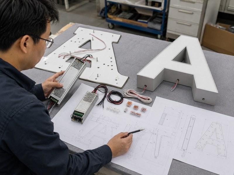
Before fabrication, confirm the approved artwork, final dimensions, wall material, wall flatness, lighting method, mounting system, standoff requirements, wire exits, power location, electrical configuration, waterproofing needs, installation access, destination market, and project schedule. Uneven-wall projects also require usable façade photographs and depth information because the mounting structure cannot be reliably developed from a logo and overall width alone.
Wall and Site Information
“Install on an exterior wall” is not enough information for an engineered channel-letter project. The manufacturing team should understand what the visible surface is, how irregular it is, what structure lies behind it, and what restrictions the local team may face when drilling, wiring, sealing, or accessing the rear of the façade.
The wall description should identify whether the installation surface is concrete, brick, stone, metal panel, ACP, EIFS, glass, curtain wall, timber, lightweight partition, or another construction. It should also state whether that surface is flat, textured, ribbed, deeply jointed, curved, stepped, recessed, or interrupted by trim and other building elements.
For exterior projects, exposure also matters. Rain, ultraviolet light, temperature changes, coastal corrosion, dust, and cleaning conditions influence materials, cable entries, fasteners, surface protection, drainage, and waterproofing details.
Site dimensions should go beyond the available sign area. Useful information includes the finished centerline or baseline, distance to architectural edges, maximum known projection, recessed zones, clearance from canopies and lighting fixtures, and the location of available power.
A mounting solution can also affect logistics. A larger backboard or raceway may simplify installation while increasing package size and weight. That trade-off should be assessed before production rather than after the mounting structure has already been fabricated.
Product and Electrical Information
A channel-letter quotation becomes more reliable as the project inputs become clearer. iduoduo’s documented inquiry checklist contains up to 20 project variables, including logo files, dimensions, lighting, colors, letter depth, environment, voltage, mounting system, wall condition, waterproofing, destination, packaging, and schedule.
| Project Item | Why It Matters on an Uneven Wall |
| Logo or Font File | Controls letter geometry and mounting positions |
| Overall Size | Determines how far the sign spans wall variation |
| Letter Height | Affects weight and mounting requirements |
| Lighting Type | Changes spacing, wiring, and back-wall needs |
| Letter Depth | Affects projection and optical performance |
| Indoor or Outdoor | Influences materials and weather protection |
| LED Color or CCT | Establishes the lighting specification |
| Voltage | Determines power configuration |
| Mounting Method | Defines how the sign meets the building |
| Raceway or Backboard | May become the leveling structure |
| Wire Exit | Must avoid wall and structural conflicts |
| Wall Type | Influences installation and anchor planning |
| Waterproofing | Affects penetrations and cable entries |
| Destination Market | Can affect electrical configuration |
| Project Date | Influences production and installation planning |
Not every project begins with all of these details. A manufacturer can review a logo, photographs, and approximate size at an early stage and help identify the missing information. The important point is that critical variables should be confirmed before the production drawings are released.
Electrical design deserves the same attention as letter geometry. Low-voltage wiring, power-supply location, cable length, service access, wall penetrations, dimming or controls, and the location of mains power can all affect the mounting system. A raceway or backboard may be selected partly because it creates a practical place to organize these components rather than because the letters themselves require it.
Responsibility Boundaries
A professional sign manufacturer can engineer the product interface in detail, but it cannot fully inspect a building located thousands of kilometers away from a factory. Keeping that boundary clear improves project reliability rather than reducing the manufacturer’s value.
The manufacturing side can prepare stud positions, mounting holes, letter dimensions, backboard or raceway drawings, wire-exit drawings, power information, product weights, templates, accessories, and installation references. These materials give the local team a controlled product to work with and reduce the amount of improvisation required at the site.
The local installer, contractor, architect, or qualified engineer should confirm the actual wall construction, hidden services, structural capacity, suitable anchors, waterproofing interface, curtain-wall restrictions, local regulations, and any required engineering approval. This is especially important for high-rise façades, stone cladding, lightweight partitions, curtain walls, high-wind locations, and projects where the mounting structure connects to major building components.
That division prevents a common misunderstanding: a detailed manufacturing drawing is not automatically a structural approval for every building. A strong manufacturer reduces uncertainty at the product-to-building interface while the local construction team validates the conditions that only a site inspection can confirm.
How Do You Reduce Installation Risk?
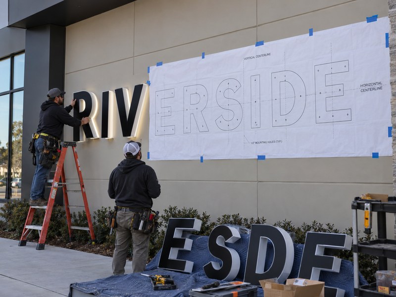
Installation risk is reduced by completing the difficult decisions before fabrication. Mounting holes, stud positions, spacers, wire exits, power locations, templates, waterproofing details, hardware interfaces, product identification, and accessories should all match the approved mounting strategy. The installer should receive a predictable sign system, while still rechecking the physical site because even a good drawing cannot account for unreported building changes.
Holes, Studs, and Wire Exits
Small mounting details often create the largest delays because they are easy to overlook during design and difficult to change once finished letters are on site. A sign may have the correct color, perfect acrylic faces, and uniform LEDs, yet still require costly rework because a stud is too short, a cable exit collides with a metal member, or the drilling pattern crosses an inaccessible joint.
Before drilling, the local team may need to confirm electrical cables, water pipes, framing, wall cavities, curtain-wall members, stone joints, glass, existing power points, anchor depth, and waterproofing membranes. These conditions are normally invisible in a storefront photograph.
Hole tolerance also deserves attention. A hole that is designed too tightly can make installation difficult if drilling varies by a few millimeters. An excessively loose hole can make accurate positioning harder. The correct tolerance should provide realistic site flexibility without allowing the letters to lose alignment.
Exterior penetrations require another layer of control because each opening can become a potential water path. Stud holes, wire exits, raceway fixings, backboard fixings, and structural brackets need compatible sealing, drainage, and installation practice.
For complicated façades, reducing the number of penetrations may sometimes create more value than reducing the amount of metal in the mounting system. A raceway or backboard can add fabrication cost but substantially reduce drilling, wiring, alignment, and rework at the building.
Installation Templates
An installation template is one of the most useful links between the approved artwork and the physical façade. A good template does more than show the outer shape of the letters. It organizes their relationship as a complete wordmark and helps transfer the approved geometry to the building.
iduoduo’s engineering documentation states that an installation template can control letter position, spacing, level, hole locations, wire exits, total dimensions, and logo proportions. It can also identify orientation, store or product numbers, centerlines, total width, wire positions, and segmented areas.
The same documentation also states an important limitation: the template cannot replace site verification.
That distinction is particularly important on uneven walls because a template is essentially two-dimensional while the building surface is three-dimensional. The installation team should position and level the pattern, verify overall dimensions, identify every proposed fixing point, compare those locations with the actual substrate, check electrical exits, confirm spacers or structural supports, and only then begin drilling.
For multi-store programs, this approach also protects brand consistency. The letter spacing, proportions, and logo geometry can remain standardized while the site-specific mounting structure is adjusted for each building.
Pre-Production Check
Before production begins, the team should be able to answer one practical question: if the completed channel letters arrived at the site tomorrow, could the installation team understand how they are meant to sit, align, wire, seal, and connect to this particular building without redesigning the product?
A useful review covers the artwork, final dimensions, wall information, mounting method, lighting configuration, electrical system, installation interfaces, and delivery requirements. The logo, font, spacing, letter height, wall texture, standoff depth, Raceway or Backboard, wire exits, power-supply location, template, accessories, packaging, segmentation, and project schedule should all refer to the same approved version.
iduoduo can support the installation stage with mounting templates, hole-position drawings, wire-exit drawings, Raceway drawings, power-circuit information, product numbering, accessory lists, lighting videos, and remote installation communication. The local installation team remains responsible for final site verification and construction.
This process is especially valuable when the façade is irregular because the installation crew has fewer opportunities to rely on the wall itself as a reference. The mounting system needs to carry more of the geometric control.
The main lesson is simple: an uneven wall is not an unexpected complication if it is treated as an engineering input from the start. It only becomes expensive when the sign is designed first and the building is considered later.
Designing channel letters for an uneven wall is therefore less about finding a single special bracket and more about coordinating several ordinary decisions correctly. Wall geometry, finished projection, mounting method, wire routing, optical performance, penetration control, templates, and local installation responsibility all need to work together. When they do, the finished sign can look clean and intentional even when the surface behind it is anything but flat.
For commercial projects, the most reliable starting point is to share the logo, target size, wall photographs, known wall material, preferred lighting method, installation area, and electrical conditions before the structure is finalized. iduoduo can then review how the channel letters, standoffs, Raceway, Backboard, wiring, and installation interface should be developed around the actual project rather than forcing a standard configuration onto a difficult façade. The objective is not to make the sign more complicated; it is to remove complications before they reach the jobsite.
Frequently Asked Questions
Can Channel Letters Be Installed on a Brick Wall?
Yes. Channel letters are frequently installed on brick, but the brick condition matters more than the material name alone. A relatively even brick façade may support direct or standoff mounting, while deep mortar joints, projecting bricks, repaired areas, or limited access behind the wall can make a Raceway or Backboard more practical. Final anchors should be selected for the actual wall construction, product weight, installation height, and local requirements rather than chosen only because the visible surface is brick.
What Mounting Method Is Best for a Very Uneven Wall?
For a very uneven wall, a Backboard or Raceway is often easier to control than mounting every letter independently, although the final choice depends on the architecture and desired appearance. A Backboard provides a continuous mounting and visual plane, while a Raceway centralizes the letters, wiring, and power components on one structural enclosure. If the variation is smaller and well documented, project-specific standoffs may preserve a cleaner individual-letter appearance without requiring a full panel behind the sign.
Do Halo-Lit Channel Letters Need a Flat Wall?
They do not require a perfectly flat wall, but the wall condition strongly affects the halo. Reverse-lit letters rely on reflected light, so different distances between the letter and the wall can produce different halo widths and brightness levels. Wall color and texture also matter. Rough stone, deep brick joints, ribbed panels, or dark surfaces may require adjusted standoffs or a controlled Backer surface to achieve a more predictable and visually balanced glow across the entire logo.
How Far Should Halo-Lit Letters Sit From the Wall?
A common iduoduo engineering reference for halo-lit letters is approximately 20–50 mm, but the final distance depends on letter height, stroke width, return depth, LED layout, wall color, surface texture, ambient lighting, and the desired halo width. The correct spacing should therefore be treated as a project decision rather than a fixed industry rule. Large exterior letters and small reception logos may need noticeably different optical relationships.
Is a Raceway Better Than Direct Mounting?
A Raceway is not automatically better, but it can be more practical when wiring access is limited, numerous individual wall penetrations are undesirable, or the façade is difficult to work with. Direct mounting generally provides the cleanest floating-letter appearance, while a Raceway centralizes wiring and power and gives the installer a shared structure to attach to the building. The decision should compare visual requirements, wall conditions, installation time, maintenance access, electrical routing, and the cost of potential site rework.
Can an Installation Template Solve an Uneven Wall Problem?
An installation template helps control letter position, spacing, level, hole locations, wire exits, total dimensions, and logo proportions, but it cannot make a three-dimensional wall flat. It transfers the approved sign geometry to the site, while spacers, raceways, backboards, brackets, and anchors solve the physical connection to the building. iduoduo’s engineering documentation specifically states that the template does not replace field verification, so the installation team should still check the actual substrate before drilling.
What Information Should I Send Before Ordering Channel Letters for an Uneven Wall?
Start with the logo file, approximate sign size, clear front and angled wall photographs, wall material, indoor or outdoor location, preferred lighting effect, installation height, available power, destination country, and any known depth variation. If available, include façade drawings, measurements, electrical locations, and installer comments. Better site information allows the mounting method, wire exits, standoff depth, Raceway or Backboard, waterproofing details, packaging, and installation documents to be developed before production instead of being corrected after delivery.