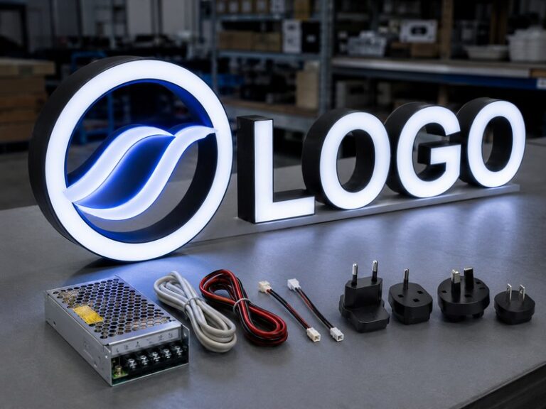

A dark section inside a channel letter often looks like a simple lighting problem, but experienced sign technicians rarely begin by removing the first LED module they can reach. A channel letter is a complete illuminated system made up of LEDs, low-voltage wiring, connectors, a power supply, a face or back panel, a metal return, mounting hardware, weather protection, and sometimes a raceway or backboard. A fault in any one of those areas can make the symptom look like an LED failure. Replacing the wrong component may restore the light temporarily, create a visible brightness mismatch, or leave the original electrical or moisture problem untouched.
Replacing LEDs inside channel letters safely starts by disconnecting power, identifying what has actually failed, recording the original module and wiring configuration, selecting an electrically and optically compatible replacement, opening the letter through its intended service access, installing the new modules, testing the complete illuminated letter, and restoring the enclosure. The replacement must match the existing system rather than simply fit into the available space.
This distinction becomes much more important on commercial storefronts, hotels, restaurants, retail chains, and multi-location projects. Imagine replacing one LED module in a letter mounted six metres above a storefront and discovering three days later that the new module is noticeably cooler in colour than the remaining LEDs. The module itself may cost very little compared with another lift rental, another technician visit, another access arrangement with the store, and another evening when the brand sign does not look consistent. The real objective is therefore not simply to make a dark letter light again. It is to restore the sign as a stable electrical, optical, structural, and weather-protected system.
How Do You Know What Has Failed?

A dark channel letter does not automatically mean its LED modules have failed. Start with the pattern of the fault. One local dark area often points toward a module, connector, or short section of wiring, while a whole letter, several letters, repeated flickering, or a failure that appears after rain can indicate a power supply, branch circuit, connection, voltage, or moisture problem.
Read the Failure Pattern
The first useful diagnostic tool is often the illuminated sign itself. Step far enough away to see the complete word or logo rather than concentrating immediately on the affected letter. A small dark patch surrounded by normally illuminated areas suggests a local problem. A whole letter that is completely dark may indicate a loss of feed to that letter, while several letters failing at the same time increases the possibility of a shared power supply, common wiring path, controller, or raceway connection.
Flickering deserves separate attention because it can behave differently from a completely failed module. If several modules or letters flicker together, unstable power, a loose electrical connection, excessive load, voltage drop, or a deteriorating power supply should be considered before replacing individual LEDs. A sign that works when first switched on but begins flickering after extended operation may also be showing a heat-related electrical problem rather than a straightforward LED failure.
The timing of the problem matters as much as its location. Ask whether the failure appeared suddenly, gradually became dimmer, happens only after rain, occurs during very hot weather, or started after another repair was completed. Those details can narrow the investigation considerably. Photographs taken with the sign off and illuminated, together with a short video showing flickering or intermittent behaviour, provide a better service record than a simple note saying that one letter is not working.
iduoduo’s documented Channel Letter after-sales process follows the same system-level approach. Diagnosis considers the LED modules together with the power supply, wiring, voltage, installation condition, water ingress, environment, transportation history, and operating time instead of automatically classifying every lighting fault as an LED problem.
| Visible Condition | Check First | What It Does Not Prove |
| One small dark area | LED module, connector, local wire | The entire power supply has failed |
| One complete letter dark | Letter feed, branch wiring, module chain | Every LED in the letter failed together |
| Several letters dark | Shared supply, wiring, raceway distribution | Each letter has a separate module fault |
| Intermittent flickering | Connections, supply stability, load | Brighter LEDs are required |
| Far end appears dim | Voltage drop, wiring length, connections | More LEDs should automatically be added |
| Failure follows rain | Seal, wire entry, connector, corrosion | Normal LED ageing is the only cause |
Separate LED and Power Faults
A good diagnosis answers two separate questions: which component has stopped functioning, and what caused that component to fail? The second question is important because a replacement module can fail again if the original cause remains inside the letter. With the electrical system safely isolated, inspect the affected area for loose modules, damaged lenses, overheated conductors, corroded terminals, brittle insulation, detached adhesive, wet connectors, or evidence that the module has moved away from its intended mounting surface.
The relationship between the failed area and the surrounding modules is useful. If one module is dark while the modules immediately before and after it remain stable, a local fault becomes more likely. If an entire group connected through the same feed is dark, the problem may be upstream of those modules. Removing all of the dark modules before checking the circuit can destroy valuable evidence about how the original system was wired.
Power-supply faults can also imitate LED failures. A supply may fail completely, become unstable, or struggle when the connected load, wiring resistance, temperature, or connections are outside their intended condition. An experienced technician therefore looks at the complete powered group before deciding what to replace. When the same supply feeds several letters and every one of those letters develops similar symptoms, it makes little sense to begin by changing random LED modules.
The most efficient service process moves from the broadest shared component toward the smallest local component. That approach reduces unnecessary parts replacement and makes the repair easier to explain and document for future maintenance.
Look for Moisture and Corrosion
Moisture is one of the most common reasons a simple LED replacement turns into a repeated repair. Water can enter through an ageing face joint, damaged rear panel, loose fastener, unprotected wire penetration, deteriorated sealant, poorly protected connector, or wall opening. Condensation can also occur inside an outdoor enclosure even when there is no obvious leak, particularly where temperature changes are large.
Inspect the lowest areas of the letter carefully because water and corrosion often collect there first. Green or white deposits on copper, rust around fasteners, staining on the letter back, wet adhesive, oxidised connectors, discoloured wires, or repeated failures in the same lower section should change the repair plan. Installing new LEDs into an enclosure that remains wet is unlikely to provide a dependable result.
Sealing also requires judgement. Outdoor letters may contain intentional drainage paths, so applying sealant to every visible opening can make the problem worse by trapping water that previously had somewhere to escape. Effective weather protection combines controlled sealing, suitable components, protected electrical joints, correct installation direction, corrosion-resistant materials, and drainage where the construction requires it.
If the failure repeatedly appears after heavy rain, the lighting problem is only part of the diagnosis. The enclosure, connection protection, wall penetration, and drainage arrangement need to be checked before the repair can be considered complete.
What Should You Check Before Replacement?

Before removing any LED module, confirm that the electrical system is safely isolated, identify the operating voltage, record the original module specification and layout, and decide how much of the lighting system actually needs replacement. These checks prevent one of the most common service mistakes: installing a module that physically fits but does not match the existing electrical or optical design.
Isolate the Electrical System
Channel-letter LED modules normally operate from low-voltage DC after the power supply, but that does not mean every electrical component encountered during service is low voltage. The power supply connects the LED system to the building electrical system, and raceways, remote power-supply locations, or service boxes may contain equipment that requires qualified electrical work. The visible LED voltage therefore should never be used as proof that the entire sign is safe to handle.
Switching the sign off through a timer, remote control, photocell, dimmer, or normal operating switch is also not the same as positively isolating the electrical source. The applicable site safety procedure should be followed, unintended re-energisation should be prevented, and isolation should be verified before wires or electrical components are disturbed. Local electrical rules and the equipment manufacturer’s instructions always take priority over a generic service sequence.
Physical access adds another layer of risk. A module located inside a letter on a workbench is very different from the same module installed above a shop entrance, on a roof edge, or several storeys above the ground. Aerial lifts, ladders, traffic, public access, weather, and façade conditions can make a technically simple repair unsuitable for casual maintenance.
For that reason, deciding who performs the work is part of the repair process. A clearly identified low-voltage module replacement at an accessible location may be straightforward for trained sign personnel, while uncertain primary wiring, high-level access, damaged electrical enclosures, or extensive water ingress should be handled by appropriately qualified technicians.
Record Voltage and Module Details
Do not choose replacement LEDs by appearance alone. Channel-letter lighting systems commonly use different low-voltage platforms, with 12 VDC and 24 VDC among the widely encountered configurations. The correct value should be confirmed from the module label, power-supply output label, project drawing, installation record, or original production data rather than guessed from wire colour or connector shape.
Voltage is only the first specification to record. Note the module manufacturer and model where available, light colour or colour temperature, module wattage, lens configuration, dimensions, wire polarity, connector type, mounting method, and number of modules connected to each electrical section. Photograph labels before they become unreadable or disappear during removal.
The letter itself also provides important optical information. Record its approximate internal depth, the width of illuminated strokes, distance between modules, number of rows, position around corners, and the type of face or diffuser. Two modules can use the same voltage yet produce very different results because their lens design and light distribution are different.
For repeat or multi-location projects, these records can greatly reduce future troubleshooting time. iduoduo’s documented production controls can retain information such as LED model, LED colour, colour temperature, module spacing, letter depth, face information, illuminated photographs, and testing records for later reference.
| Item to Record | Unit or Detail | Practical Reason |
| System voltage | VDC | Prevents incompatible module selection |
| Module power | W/module | Helps verify total electrical load |
| Colour temperature | Kelvin | Reduces visible white-colour mismatch |
| Module spacing | mm or in. | Helps reproduce the original optical layout |
| Letter depth | mm or in. | Determines available light-mixing distance |
| Wire polarity | Positive / negative | Prevents incorrect DC connections |
| Module orientation | Photo or drawing | Preserves beam direction |
| Environment | Indoor / outdoor | Affects module and connection protection |
Decide the Repair Scope
The smallest possible repair is not always the lowest-cost repair over the life of the sign. Replacing one failed module can be the correct choice when the installation is relatively new, the surrounding LEDs are stable, and the original or a closely matched replacement remains available. In that situation, a local repair can restore the letter without changing its overall lighting character.
Older signs require more judgement. LED output and colour can change gradually over time, even when the modules are still operating. A new module installed beside several older modules may therefore create a noticeably brighter or cooler patch behind the same acrylic face. The electrical repair may be correct while the visual result still looks poor from the street.
Repeated failures in the same letter are another reason to reconsider the scope. If several modules from the same generation have failed over a short period, continuing to replace them one at a time can create an expensive series of service calls. The cost of access equipment, labour, travel, store coordination, and repeated disruption can easily exceed the cost difference between a spot repair and refreshing the complete lighting section.
For multi-location brands, the decision should also consider repeatability. A standard replacement module or approved retrofit family can make future service more predictable across many stores, while a one-off substitute selected only because it was locally available may create inconsistent lighting from one location to another.
How Do You Access LEDs Inside Channel Letters?

LED access depends on how the channel letter was designed and assembled. Trim Cap, trimless, halo-lit, flush-mounted, backboard-mounted, and raceway-mounted letters can place faces, backs, fasteners, wiring, and power components differently. Identify the construction before removing panels or sealant so the repair does not damage the letter or create a new weather-protection problem.
Trim Cap and Trimless Letters
Traditional front-lit Trim Cap letters often provide relatively direct access because the translucent face is held at the front of the metal return by a visible trim system. After the correct fasteners are removed, the face assembly can usually be taken away to expose the LED modules mounted inside the can. This familiar construction is one reason Trim Cap letters can be convenient for certain types of field service.
The face still needs careful handling. Older acrylic can become brittle, particularly near screw holes and corners, and larger faces can flex when unsupported. Before removal, photograph screw positions, trim joints, face orientation, and any sealing details. Keep the fasteners associated with the correct letter rather than mixing hardware from multiple characters.
Trimless letters can look simpler from the outside but may require more care during service because manufacturers use different methods to achieve the clean front edge. Hidden fasteners, bonded systems, removable rear panels, concealed screws, or custom face-retention details may all be involved. Applying a traditional Trim Cap removal method to a trimless letter can damage the acrylic edge or finished metal return.
iduoduo’s Channel Letter engineering records distinguish Trim Cap and Trimless construction as different structural systems, with Trim Cap specifically offering easier access for some maintenance situations. The general lesson is straightforward: identify the intended service path before applying force.
Halo-Lit Access
Halo-lit channel letters operate differently because their light is directed toward the mounting surface behind the letter. LEDs may therefore be arranged near a rear panel or internal back surface, while studs, stand-offs, spacers, concealed wire penetrations, and mounting hardware become more important during service.
Some halo-lit letters allow rear access without completely removing the letter, while other installations require the character to be loosened or taken away from the wall. Before disturbing the mounting system, record the stand-off distance, spacer locations, stud positions, wire exit, and orientation of the back panel. These details influence more than reinstallation convenience.
The distance between the letter and the wall directly affects the shape and intensity of the halo. Reinstalling the letter noticeably closer to or farther from the wall can change the illuminated appearance even when the LED modules remain identical. Wall colour, texture, and reflectivity also affect the final effect, which is one reason halo lighting should be judged after the letter is returned to its intended position.
Wall penetrations deserve particular attention during removal. A wire opening that was originally protected can become a source of water ingress if the letter is moved and the surrounding seal is damaged. Restoring those penetrations is part of the repair, especially on outdoor installations exposed to wind-driven rain.
Raceway and Backboard Access
Raceway-mounted channel letters place multiple letters onto a common enclosure that can contain power supplies, low-voltage distribution, connectors, and mounting hardware. This design can make certain service tasks more accessible, but it also changes the order of diagnosis. If several letters on the same raceway fail together, the shared electrical components should be checked before every individual letter is opened.
Understanding circuit grouping is particularly useful. If five letters are mounted on one raceway but only three connected to one output are dark, the location of the fault may become obvious once the wiring groups are identified. Clear labels inside the raceway can therefore reduce service time significantly, especially years after the original installation when the technician may have had no involvement in production.
Backboard-mounted systems offer similar opportunities to organise power distribution and wiring behind the visible letters. However, the exact arrangement varies by project. Product drawings, wiring records, and installation photographs are more dependable than assumptions based solely on the outward appearance of the sign.
This is also an important design lesson for new projects. Maintenance access should be considered before production rather than after the first failure. A sign that looks clean but requires extensive façade disassembly every time a power supply needs inspection may have higher lifetime service costs than a design that includes planned access from the beginning.
How Do You Replace LED Modules?

Once the failed component and replacement specification are confirmed, photograph the existing module pattern, remove only the necessary components, prepare the mounting surface, install the new modules according to the correct optical layout, reconnect the low-voltage wiring, and inspect every connection before testing. The goal is uniform, stable illumination, not simply an LED that turns on.
Document Before Removal
Photograph the complete open letter before cutting or disconnecting any wires. Then take closer photographs showing module position, spacing, direction, polarity, junction points, branch wiring, and areas where the module pattern changes around corners or narrow strokes. A simple ruler placed beside the modules in one photograph can provide useful scale information later.
Irregular logos benefit from a quick sketch as well. Mark which modules belong to each electrical section and note whether wide strokes use parallel rows. Once the original modules have been removed, details that seemed obvious during disassembly can become difficult to reconstruct accurately.
Good documentation also separates a repair from an unnecessary redesign. If an equivalent module is still available, reproducing the proven pattern is often the most predictable approach. If the original module has been discontinued, the recorded information allows the replacement to be evaluated against the old letter depth, spacing, face material, wiring, and optical performance.
This becomes especially valuable for chain-store programs. A photograph, module model, voltage record, spacing measurement, power-supply specification, and final illuminated image can form a simple service file for each sign generation. The next technician then begins with known data rather than reopening the letter simply to discover what is inside.
Remove and Prepare
LED modules are commonly attached using pressure-sensitive adhesive, screws, rivets, or a combination of mechanical and adhesive fixing. Remove any mechanical retention first and lift the module carefully rather than pulling it free by its conductors. Keeping useful wire length makes the replacement connection easier and reduces the chance of creating new strain on the circuit.
Once the failed module is removed, inspect the mounting surface. Dirt, oil, water, corrosion, loose paint, failed adhesive, or damaged coating can explain both electrical and optical problems. A module that has detached from the back of the letter may move closer to the face and produce a hotspot even if the LEDs themselves remain functional.
The mounting surface should be cleaned and dried according to the replacement module manufacturer’s instructions. Adhesive-backed modules depend on suitable surface preparation, and installing them onto moisture, dust, oily residue, or deteriorating coating reduces long-term reliability.
Extensive corrosion or water staining is a warning that the repair should not continue as a simple parts swap. If the sign enclosure or electrical connections have deteriorated, the underlying condition needs to be corrected before new modules are installed. Otherwise the repair may only hide the problem temporarily.
Install and Reconnect
When an equivalent module is being used, reproduce the original module positions as closely as practical. When switching to a different module family, follow the new manufacturer’s optical density and depth guidance rather than copying the old spacing automatically. Different lenses, power levels, and beam patterns can require different layouts even when the physical module size is similar.
Avoid adding extra modules simply because more light seems safer. Excessive LED density can increase electrical load, produce visible bright points, increase heat, and create uneven illumination without improving the quality of the sign. The correct layout balances brightness, spacing, letter depth, face diffusion, and power consumption.
Keep modules securely mounted and wires organised away from screw holes, panel edges, sharp metal, and places where the face or back panel can pinch them during reassembly. Connections should follow the module manufacturer’s polarity and connector instructions. Wire colour can be useful, but markings and documented polarity are more dependable when the original wiring history is uncertain.
After reconnecting the low-voltage system, inspect the complete letter before test energisation. Remove clipped wire ends, loose screws, unused metal parts, and tools. If the repair reaches the building-side AC wiring, an unidentified power-supply input, or damaged mains components, the work should be transferred to properly qualified electrical personnel.
Which Replacement LEDs Should You Choose?

Choose replacement LEDs according to electrical compatibility, light colour, optical distribution, letter depth, face material, mounting method, and installation environment. A physically smaller or brighter module is not automatically an upgrade. The most suitable replacement is the one that integrates correctly with the existing power system and produces a consistent illuminated appearance through the finished letter face.
Match Voltage and Load
System voltage is the first technical filter. Channel-letter module systems are available in several configurations, with 12 VDC and 24 VDC commonly encountered in commercial signage. The existing letter should therefore be checked rather than assumed to use a particular voltage. A 24 V module should not be installed into a 12 V circuit simply because its connector or module body looks similar.
Module power also matters. If a replacement family consumes a different number of watts per module, the original power-supply calculation may no longer be valid. The module manufacturer’s load tables, permitted module counts, and power-supply instructions should be used whenever the lighting system changes.
Long low-voltage cable runs can also affect performance. If illumination becomes progressively weaker toward the end of a circuit, voltage drop or poor connections may be more relevant than module quantity. Installing additional LEDs on an already weak circuit can increase the load and make the underlying issue worse.
For a small repair using an equivalent module, the original electrical design can often be preserved. For a full retrofit using another LED family, the project should be treated as a lighting-system change rather than a simple component substitution. Module count, power supply, wiring distribution, and optical spacing may all need to be reviewed together.
Match Colour and Optics
The word “white” is not precise enough for replacement lighting. Commercial sign LEDs are available across warm, neutral, and cool white ranges. As a general reference, warm white products are often around 2700-3500 K, neutral white around 4000 K, and cooler signage whites frequently fall around 5000-6500 K or higher. Exact offerings vary by manufacturer, so the original specification remains the best reference.
Even matching the stated Kelvin value does not guarantee that a new module will look identical beside LEDs that have operated for years. LED output can change with age, while the acrylic face may also accumulate dirt, weathering, or colour change. The new module should therefore be judged through the actual face rather than by looking directly at the exposed LEDs.
The beam pattern is equally important. Shallow letters provide less distance for individual light points to blend before they reach the face, so optical distribution becomes critical. Deeper letters provide more mixing space but may require different density or output to achieve the desired brightness.
iduoduo’s engineering data reflects this relationship by considering letter or product depth, stroke width, face or diffuser characteristics, LED beam angle, environmental conditions, and brightness requirements when planning LED placement.
| Parameter | Common Reference | What to Confirm Before Replacement |
| Low-voltage system | Often 12 VDC or 24 VDC | Existing module and power-supply labels |
| Warm white | Approx. 2700-3500 K | Original approved light colour |
| Neutral white | Approx. 4000 K | Match against existing illuminated letter |
| Cool white | Approx. 5000-6500 K+ | Brand appearance and neighbouring letters |
| Module spacing | Product-specific | Manufacturer layout guidance |
| Letter depth | Project-specific | Available LED-to-face mixing distance |
| Module power | Product-specific watts | Total load on each power supply |
| Optical beam | Lens-specific | Hotspot and dark-zone performance |
These ranges are practical references rather than universal product standards. The selected module manufacturer’s current technical documentation and the existing sign specification should determine the final replacement.
Match the Environment
Outdoor suitability should never be judged only from the rating printed on one LED module. The complete channel-letter system includes LEDs, connectors, wire joints, power supplies, enclosure panels, fasteners, wire exits, coatings, seals, drainage, and wall penetrations. The weakest part of that system can determine how reliably the sign performs outdoors.
Environmental conditions also vary widely. A storefront in a relatively dry climate is exposed differently from a sign installed close to the sea, in a high-humidity area, on a façade receiving strong afternoon sun, or in a region with repeated freeze-thaw cycles. The same module can experience very different operating conditions depending on the enclosure and installation.
Repeated failures in one area of the sign should trigger an environmental inspection. If the lowest part of one letter repeatedly develops corroded connectors, changing to another LED module brand may not address the actual problem. Drainage, water entry, conductor protection, and installation orientation may deserve more attention.
iduoduo’s outdoor-sign engineering approach likewise considers LED modules together with power supplies, connectors, wire exits, sealing, drainage, coatings, fasteners, condensation, thermal expansion, ultraviolet exposure, corrosion, and maintenance access. This broader view is useful during both product development and field repair because outdoor reliability is created by the system, not one component.
How Do You Test and Reseal the Letter?

Test the repaired letter before final closure and then evaluate it again through the installed face from a realistic viewing distance. Check for stable operation, flicker, dark areas, hotspots, colour mismatch, and abnormal behaviour. Once the lighting is correct, restore the face, back, fasteners, wiring protection, seals, penetrations, mounting details, and drainage to their intended condition.
Test the Complete Letter
Seeing a replacement module illuminate with the face removed proves only that the module receives power. It does not prove that the repaired letter looks correct as a finished sign. The important test happens when the optical system is returned to something close to its normal operating condition.
After completing the required safe procedure for test energisation, observe whether all repaired modules start normally and remain stable. Look for intermittent flicker, delayed starting, changes in output, or a section that behaves differently after the sign has been operating for a period. If a fault reappears only after warm-up, additional diagnosis may be needed.
Temporarily refit or correctly position the face before judging uniformity. Diffusing acrylic changes the appearance dramatically, and a layout that looks acceptable with exposed modules can produce bright spots once the letter is closed.
The sign should also be viewed from the distance at which customers normally see it. Small optical variations that appear dramatic from a few centimetres away may be invisible from across a car park, while a colour mismatch between two large letters can remain obvious at considerable distance. Commercial service decisions should reflect the actual viewing condition.
Check Uniformity and Connections
Hotspots appear as unusually bright areas where individual modules or rows are too visible through the face. Dark areas can result from insufficient optical coverage, module failure, poor spacing, shadowing from internal structures, or a weak electrical connection. Neither condition should automatically be solved by adding or removing LEDs until the actual cause is understood.
Compare the repaired letter with adjacent characters. A technically functional replacement may still be unacceptable if the new section is significantly brighter, warmer, or cooler. This is particularly noticeable with white acrylic faces, simple geometric logos, and signs installed in darker nighttime environments.
Inspect wiring again after the test because movement and heat can expose problems that were not obvious during initial assembly. Connections should remain secure, conductors should stay clear of sharp edges, and no wire should be positioned where the face, trim, back panel, or raceway cover can pinch it.
At the manufacturing stage, iduoduo uses 100% lighting inspection followed by a 72-hour pre-shipment test for illuminated products, checking areas such as LED stability, power stability, flickering, colour variation, local dark zones, temperature behaviour, and wiring connections. A field repair does not necessarily require the same factory test duration, but the categories being checked provide a practical framework for evaluating repair quality.
Restore the Enclosure
Reassembly is part of the technical repair rather than cosmetic finishing. Reinstall the face, back, trim, spacers, fasteners, and other components in their correct positions. Make sure that wires remain inside their intended routing and are not trapped between panels or under screws.
Inspect any area disturbed during access. Old sealant may separate from the metal or acrylic when a panel is removed, and an originally protected wire penetration can become vulnerable after a letter has been taken away from the wall. Replace deteriorated sealing materials where appropriate to the original construction while keeping any designed drainage route open.
Halo-lit letters should be returned to their original stand-off distance because this controls the halo spread. Raceway and backboard covers should close securely, and service enclosures should be left free of loose screws, cut wire ends, and unused parts.
Finish the job with a final illuminated photograph and a simple service record. Record the date, affected letter, failure symptom, replacement LED model, system voltage, power-supply information, work completed, and any evidence of moisture, corrosion, or structural deterioration. For a single shop, this information makes the next repair easier. Across a chain of stores, it can reveal repeated component or installation patterns that would otherwise remain invisible.
Replacing LEDs inside channel letters is therefore much more than removing a failed light source. A reliable repair begins by reading the failure pattern, confirming the electrical condition, preserving the original optical logic, selecting a compatible replacement, testing the complete letter, and restoring the enclosure. When those steps are followed, the sign is more likely to return to consistent operation without creating new problems in brightness, colour, wiring, or weather protection.
For sign companies, brands, contractors, and multi-location projects, the strongest long-term approach is to treat service information as part of the original product specification. Keeping LED models, power-supply data, drawings, photographs, module layouts, colour references, installation details, and previous repair records makes future maintenance faster and more predictable. iduoduo applies the same principle during Channel Letter development, production, testing, and after-sales support, so replacement planning can be based on actual project information rather than guesswork.
Frequently Asked Questions
Can You Replace Only One LED Module in a Channel Letter?
Yes, a single module can often be replaced when the fault is genuinely local, the electrical system is otherwise stable, and a compatible replacement is available. The important issue is not the number of modules being replaced but whether the new module matches the existing voltage, light colour, optical output, and layout closely enough to produce a consistent finished appearance.
Older signs require more caution because neighbouring LEDs may have changed in brightness or colour after years of operation. A new module can create a visibly brighter patch even when its specification looks similar on paper. If several modules in the same letter have already failed, replacing the entire lighting section may provide a more predictable result and reduce repeated service costs.
How Do You Know if the LED or Power Supply Has Failed?
The failure pattern provides the first clue. One isolated dark area often points toward a local LED module or connection, while an entire letter or several letters failing together makes the shared power supply, branch wiring, or distribution connections more important to investigate. Flickering across several modules can also indicate unstable power rather than simultaneous LED failure.
Testing should be performed by appropriately qualified personnel using the actual module and supply specifications. The key is to avoid replacing components randomly. Confirm which modules receive the correct low-voltage supply, inspect connections and wiring, and check whether other modules on the same circuit operate normally. The diagnosis should establish both the failed component and the condition that caused the failure.
Can You Mix Old and New LEDs in the Same Channel Letter?
Old and new LEDs can sometimes operate in the same letter, but visual compatibility should be checked carefully. Even if the nominal voltage and colour temperature match, older LEDs may have lower output or a slightly different colour after extended use. A new module can therefore appear brighter or create a different shade of white through the same acrylic face.
The safest approach is to test the proposed replacement inside the actual letter and judge it with the face installed. If the difference is obvious at the normal viewing distance, replacing a larger lighting section may provide a cleaner result. Brand signage should be evaluated as a complete illuminated surface rather than a collection of individual working modules.
Are Channel Letter LEDs Usually 12V or 24V?
Both 12 VDC and 24 VDC systems are commonly encountered in commercial LED signage, so voltage should never be assumed before replacement. The existing module label, power-supply output specification, original drawing, or production record should be checked before any replacement part is selected.
Changing voltage is not a simple matter of choosing a different module. The power supply, connected modules, wiring design, and total electrical load all need to work as one system. If the original module has been discontinued and a different product family is being considered, the change may effectively become a retrofit rather than a spot repair and should be evaluated accordingly.
What Causes Dark Spots After LED Replacement?
Dark spots can result from module spacing that is too wide, an incorrect lens pattern, insufficient output, a disconnected module, an internal shadow, or a replacement LED that behaves differently from the original system. The distance between the LED and the face also plays an important role because light needs enough space to spread and blend before reaching the diffuser.
The solution is not always to add more modules. Extra LEDs can create hotspots and increase electrical load. Compare the repaired layout with the original arrangement, confirm the replacement manufacturer’s spacing guidance, check module orientation and connections, and inspect the result through the installed face. Optical problems should be corrected through layout and component matching rather than guesswork.
Should Channel Letters Be Resealed After LED Replacement?
Any seal, panel, face, wire penetration, or weather-protection detail disturbed during service should be inspected and restored as required by the original construction. Outdoor letters rely on more than sealant alone, however. Connections, drainage paths, fasteners, wire exits, mounting direction, and enclosure condition all influence how water is controlled.
Avoid sealing intentional drainage openings simply because they appear to be holes. Trapped moisture can be as damaging as direct rain entry. A proper repair restores the intended combination of sealing and drainage. If water or corrosion was present before the LED replacement, identify and correct the entry or retention point before closing the sign.
When Should a Professional Technician Replace Channel Letter LEDs?
Professional service is appropriate when the fault involves uncertain AC wiring, power-supply replacement, extensive water damage, damaged electrical enclosures, high-level access, difficult façade conditions, repeated unexplained electrical failures, or an installation where removing the letter could affect structural mounting or weather protection.
Professional assistance is also useful when the original LED system is discontinued and the replacement requires a new module family, revised layout, or power calculation. A small LED component may be inexpensive, but incorrect diagnosis can lead to repeated lift visits, damaged faces, mismatched illumination, or electrical problems. The decision should therefore consider the complete service risk rather than the price of the replacement module alone.