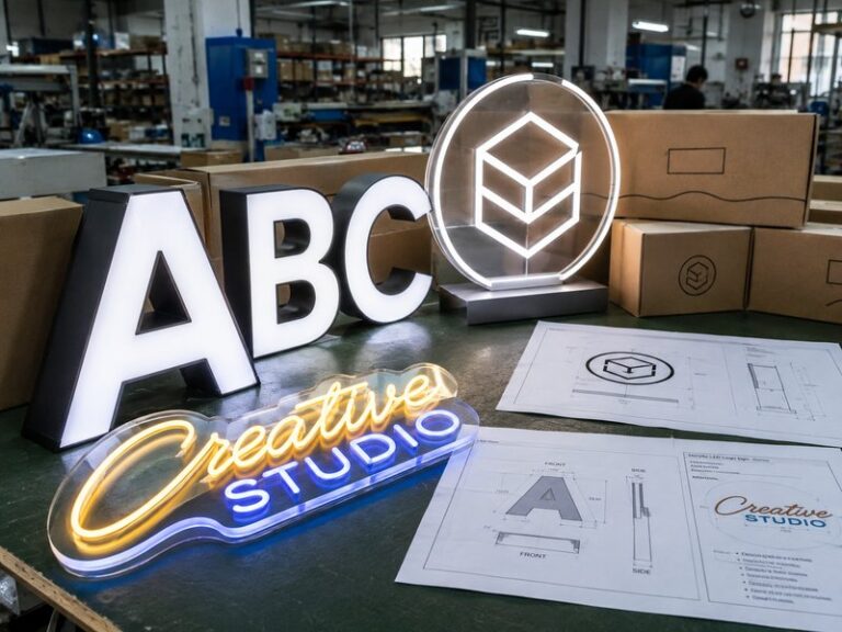

Large channel letters often look straightforward when they exist only on an elevation drawing. A logo can stretch several meters across a storefront, a script wordmark can flow smoothly from one end to the other, and a raceway can appear as one clean horizontal line. The difficulty usually becomes obvious when the finished structure has to leave the factory. The sign must fit into protective packaging, pass through freight networks, survive repeated handling, reach the actual installation area, and still be practical for the local crew to lift and position.
For this reason, dividing a large channel letter sign is not simply a matter of cutting a long product into shorter pieces. Every split changes the structure, LED arrangement, wiring, weather protection, packing method, labeling, and installation sequence. A joint that saves freight space but creates a visible break through the center of a logo can reduce the quality of the finished sign. A joint that looks perfect from the front can still create problems if installers cannot reach the electrical connection behind it.
Large channel letters should be divided into transportable sections during engineering, with split points selected according to artwork, structural strength, LED continuity, wiring, packaging dimensions, site access, and installation requirements. The best solution is not necessarily the smallest shipping package. It is the section plan that reduces freight and handling risk while allowing installers to accurately reconstruct the sign without obvious seams, weak joints, or difficult electrical connections.
Consider a connected logo that is several meters wide. It may be completely manufacturable as one piece, but the finished crate might not fit through the receiving building, the installation crew might not be able to handle its weight safely, or the local lift platform might not have enough working space. In that situation, segmentation is not evidence that the sign was poorly designed. Done correctly, it is evidence that manufacturing, shipping, and installation were planned as one continuous project rather than three separate problems.
When Do Large Channel Letters Need to Be Divided?

Large channel letters should be divided when producing and delivering them as a single piece creates unreasonable packing, freight, handling, access, lifting, or installation risk. No universal width automatically requires segmentation. The decision should consider finished dimensions, packed dimensions, weight distribution, structural stiffness, freight method, building access, installation height, available lifting equipment, and the number of joints that will be required after delivery.
Look Beyond the Finished Sign Size
One of the most common mistakes is comparing the artwork dimensions directly with transportation limits. Freight companies do not handle the dimensions shown on the sign drawing. They handle the finished package, which can be noticeably larger after foam protection, edge clearance, internal framing, plywood panels, pallets, and timber reinforcement have been added around the product.
A 3,500 mm-long structure therefore does not normally create a 3,500 mm-long shipping package. The actual crate must provide enough space to protect faces, metal returns, mounting hardware, wiring, and finished surfaces without allowing the sign to move during transport. Irregular logos may require even more unused space because the crate still needs a stable rectangular structure around a product with curves, projections, or empty areas.
Packaging requirements can therefore change product engineering. Iduoduo’s documented process specifically recognizes that packaging can influence product segmentation, removable supports, backboard dimensions, raceway length, power-supply position, connection methods, crate dimensions, local handling, and installation sequence. It also states that segmentation should be considered during design when the complete sign cannot reasonably pass through transportation channels, doorways, elevators, or other access restrictions.
The practical limit may ultimately be somewhere far from the international freight route. A crate can fit comfortably inside a container and still be impossible to move through a shopping mall corridor. A sign can arrive at the jobsite without damage and still be too large for the available boom lift. A rooftop project may be limited by a roof hatch rather than the truck that delivered the product. Good engineering considers the narrowest point in the complete delivery path.
Consider Weight, Shape, and Handling Together
Two signs with the same overall width can have completely different handling requirements. A shallow aluminum wordmark containing widely spaced independent letters may be relatively manageable, while another sign of the same width may include a continuous backboard, deep returns, internal reinforcement, multiple power supplies, and a large solid logo section. Width alone does not explain how difficult either product will be to lift or position.
Weight distribution is particularly important. A long but evenly balanced module may be easier to handle than a shorter section with most of its weight concentrated at one end. Irregular logos can also rotate unexpectedly when lifted if the lifting point does not correspond with the center of gravity. This becomes more important when installers are working from elevated equipment where there is limited space to reposition the sign.
Dividing the sign into smaller sections can reduce these handling problems, but excessive segmentation introduces a different set of risks. Every additional module creates another alignment point, structural joint, wiring interface, possible weather-protection detail, package label, hardware set, and field assembly step. The objective should therefore be to create manageable modules with the fewest practical joints rather than automatically making every section as small as possible.
Large Channel Letter structures may require internal ribs, rear frames, support members, transverse connections, or reinforced mounting areas depending on their size, materials, transport conditions, lifting method, and installation environment. Those requirements should be considered before determining the final section boundaries because reinforcement can affect both shipping weight and available joint locations.
| Project Condition | Lower Need for Segmentation | Higher Need for Segmentation | Main Concern |
| Product format | Independent letters | Connected script or logo | Continuous structure |
| Overall dimensions | Compact modules | Long integrated assembly | Crate size |
| Installation height | Ground-level storefront | High façade or rooftop | Lifting |
| Site access | Open loading area | Narrow corridors or elevators | Physical access |
| Mounting system | Individual mounting | Raceway or full backboard | Section size and weight |
| Local equipment | Crane and large crew | Small lift and limited crew | Handling |
| Freight route | Short local delivery | International freight | Packing efficiency |
| Finish | Durable textured surface | Acrylic, mirror, high-gloss finish | Damage risk |
These conditions should not be treated as automatic thresholds. They are project inputs used to determine whether one-piece manufacturing remains practical. An experienced manufacturer should review them together rather than relying on a single maximum dimension printed in a product specification.
Match the Section Plan to the Shipping Method
The planned freight method also influences how aggressively a sign needs to be divided. Small or moderate-size samples may be practical for courier services. Time-sensitive commercial projects may justify air freight. Larger channel letters, bulky raceways, wooden crates, and higher-volume orders are more commonly evaluated for freight or sea transportation, depending on project schedule and destination.
The relevant measurements are again the packed dimensions and packed weight rather than the bare sign dimensions. Iduoduo’s logistics process evaluates package dimensions, dimensional weight, quantity, wooden packaging, destination, and required project date when determining the appropriate shipping approach. A change in segmentation can therefore alter both transportation options and the final logistics cost.
However, reducing the length of the largest package does not guarantee the lowest total project cost. Three well-planned modules may dramatically improve freight and handling efficiency. Eight or ten modules might create excessive packaging, more boxes, additional accessories, longer assembly time, and more opportunities for missing parts or installation errors.
A useful review follows the sign from the factory all the way to the mounting surface: factory movement, crate construction, carrier pickup, international transportation, destination unloading, local delivery, building access, lifting equipment, façade positioning, electrical connection, and final alignment. If one stage creates a serious constraint, segmentation should be adjusted before fabrication starts.
Where Should Large Channel Letters Be Divided?

Large channel letters should be divided where the joint creates the lowest combined impact on appearance, structural integrity, illumination, wiring, waterproofing, and installation. Natural gaps, direction changes, less dominant artwork areas, independent letter boundaries, and concealed structural zones are often preferable. Highly visible centers, critical curves, narrow structural strokes, difficult LED zones, and inaccessible electrical areas should generally be avoided when a more practical split point exists.
Use Natural Visual Breaks Whenever Possible
Equal mathematical sections may be convenient for freight calculations, but they are not always appropriate for the sign itself. If a 4,800 mm-wide logo is automatically divided into three 1,600 mm modules, one of the cuts may pass directly through a prominent curve or the visual center of a brand mark. Moving the split by only a few hundred millimeters could place it inside a much less noticeable transition.
The human eye is sensitive to interrupted curves, changes in line thickness, stepped circular forms, irregular spacing, and broken baselines. This is particularly important for recognizable brand marks because viewers already know how the shape is supposed to look. A relatively small alignment difference can become surprisingly visible if it occurs in the most familiar part of the logo.
Segmentation should therefore begin with the approved vector artwork rather than the shipping crate. Several possible split zones can be identified first, after which engineering can compare them against structural and electrical requirements. Large Channel Letter and logo segmentation in iduoduo’s documented engineering process considers visual seams, structural connection, LED continuity, wiring, waterproofing, section numbering, packaging, and field assembly. The split position should avoid the main visual center whenever practical.
This does not mean appearance should override engineering. A nearly invisible joint is not useful if it weakens the frame or makes electrical assembly impossible. Visual concealment is the first filter, not the only filter. The correct position is usually the location where several requirements can be satisfied at the same time.
Treat Script Lettering and Logos Differently
Independent block letters provide natural gaps between characters, which often allows the overall sign to be divided without physically cutting through any single letter. Connected scripts are very different. One character may flow directly into the next, creating a visual structure that behaves like a single continuous object even when the underlying lettering contains several characters.
For script designs, useful division areas may occur where the stroke naturally narrows, changes direction, overlaps another element, or moves from one character into another. Even then, the narrowest visual connection is not automatically the best engineering joint. A very thin location may leave one module structurally weak during lifting or shipping, so the front artwork and rear reinforcement need to be reviewed together.
Circular, geometric, and symmetrical logos introduce another challenge because small misalignment becomes easier to notice. If two halves of a large circular mark are not perfectly aligned, the viewer may see a step or flattened area even from a considerable distance. In some cases, dividing away from the central visual axis can produce a more forgiving joint, provided the internal structure supports that location.
The design should be reviewed at both close and normal viewing distances. Close inspection reveals face gaps, return alignment, paint differences, fasteners, and surface finish. Normal viewing distance reveals whether the silhouette, baseline, curve, and brand proportions remain visually continuous. Both perspectives matter because a technically small seam can disappear with distance while a geometric error remains obvious.
Reject Split Points That Create Several Risks
A proposed joint should be reconsidered when it creates multiple difficulties at once. Cutting through a narrow stroke may reduce stiffness. Placing the joint beside a tight curve may complicate metal-return alignment. Installing a structural bracket inside a dense LED area may force an unusual lighting gap. Positioning a connection in a low point can create an unwanted place for water to collect. Hiding a fastener too effectively can make it impossible for installers to reach.
This is where a combined engineering review becomes useful. Instead of asking only whether the seam will look clean, the project team can compare each potential split across appearance, structure, lighting, electrical access, weather exposure, packing, and installation. The best position is often the one that creates no major weakness even if another option appears slightly more attractive in one category.
| Split Factor | Lower-Risk Condition | Higher-Risk Condition |
| Visual appearance | Natural artwork transition | Center of dominant feature |
| Structure | Wide supported area | Narrow unsupported stroke |
| LED layout | Adjustable module area | Dense or restricted zone |
| Electrical access | Accessible rear connection | Enclosed cavity |
| Weather exposure | Protected location | Water-catching geometry |
| Alignment | Clear reference surfaces | Complex curve |
| Installation | Reachable connection | Hidden fasteners |
| Packing | Balanced sections | One remaining oversized module |
The purpose of this comparison is not to create a rigid scoring system. It helps the manufacturer and project team recognize that a strong segmentation decision is usually a compromise between several practical requirements. Experienced engineering is valuable precisely because these requirements can conflict with one another.
How Should Split Sections Be Structurally Connected?

Split sections should reconnect through engineered alignment and reinforcement features rather than relying on decorative faces or manual positioning. Rear frames, internal braces, connection plates, brackets, locating holes, bolts, removable fasteners, and shared mounting structures can be used depending on the product. The connection should preserve the approved geometry during transport and installation while remaining accessible enough for assembly, adjustment, inspection, and future maintenance.
Build Alignment Into the Product
The installer should not have to reconstruct a large logo by comparing the pieces with a reference photograph. Alignment needs to be designed into the sign before manufacturing starts. Depending on the structure, the factory may use centerlines, matching holes, locating plates, numbered brackets, rear frame edges, installation templates, controlled gaps, or shared mounting references.
This becomes more important as the number of sections increases. A few millimeters of error at one joint may not initially appear serious, but several small errors can accumulate across a long wordmark. By the time the final section is installed, the end of the sign may be noticeably above or below the intended baseline, or the overall width may differ from the approved drawing.
Mechanical locating features reduce this accumulation because they provide repeatable reference points. They also reduce installation time. A crew that can position one section against a defined bracket or template generally works more efficiently than a crew that must repeatedly measure distances between finished surfaces.
Where possible, alignment responsibility should be carried by the rear structure rather than acrylic faces or decorative returns. Those visible components are designed primarily for appearance, enclosure, and light management. Using them as structural locating devices can introduce stress, scratching, cracking, or visible distortion.
At the same time, a field connection needs enough adjustment to deal with actual site conditions. Walls are not always perfectly flat, architectural openings may vary slightly from drawings, and existing mounting surfaces may have tolerances that were not visible during factory production. Good engineering provides positive location without making final adjustment impossible.
Reinforce the Areas That Actually Carry the Load
Structural connection is not simply about adding more metal. The important question is how forces move through the sign while it is being packed, lifted, positioned, and permanently mounted. The load path during transportation can be different from the load path after installation, which means a product that feels rigid on a wall may still need additional temporary or permanent support during shipping.
A thin decorative return may appear strong but deform when installers use it to pull two heavy sections into alignment. Acrylic faces can hold their own shape but should not be expected to carry major assembly loads. Rear frames, reinforcement plates, and support members are better suited to transferring mechanical forces across a joint.
Iduoduo’s engineering documentation identifies internal support ribs, rear frames, transverse connections, and reinforced mounting plates as possible approaches for large Channel Letter structures depending on size, materials, installation height, transportation, and lifting conditions. The exact solution should be selected around the geometry and intended installation rather than applied as a universal standard.
Engineers should consider at least three load conditions. Inside the crate, repeated vibration or tilting can place stress on unsupported extensions. During installation, a section may twist because it is held from only one or two lifting points. After installation, wall anchors or a raceway may distribute the weight more evenly. A connection that works properly in all three stages is more valuable than one optimized only for the final mounted condition.
Coordinate Raceway and Backboard Joints
Raceways and backboards can simplify installation because multiple letters are organized around a common mounting structure, but that same structure may become the largest part of the shipment. A long raceway that is easy to understand on a drawing can create a difficult crate, while a full backboard can quickly become awkward to carry through doors or lift onto a façade.
When these components need segmentation, the structural joints should be coordinated with wall fixing locations, access covers, wiring paths, letter spacing, power components, and the sequence in which installers will assemble the system. The raceway joint does not always need to sit directly below the visible lettering joint. In some cases, staggering the connections can create better support or a cleaner visual result.
Backboard-mounted signs require the same level of planning. The backboard may control the relative position of the letters, so dividing it creates a new requirement: the sections must recreate one flat, accurately aligned plane after installation. Connection plates, rear frames, controlled gaps, or locating features can help the local crew achieve this without repeatedly measuring every letter.
For internationally supplied signage, the physical connection should communicate its own logic. The installer may never have spoken with the engineer who developed the structure. Section numbering, shop drawings, hardware organization, and obvious mating points reduce dependence on verbal instructions and make installation more predictable.
How Should LEDs and Wiring Cross the Split?

LEDs and wiring should be designed around the section boundaries before manufacturing begins. Each module should have sufficient illumination near the joint, clearly identified wiring, accessible electrical connections, and an understandable relationship to the power system. LED spacing, cable exits, circuit grouping, connector positions, voltage requirements, weather protection, and service access should be reviewed together so that segmentation does not introduce dark bands or complicated field wiring.
Maintain Lighting Continuity Across the Joint
A sign can be mechanically perfect during the day and still reveal every section boundary when it is illuminated at night. If the last LED module on one section and the first module on the next are too far apart, the completed sign may show a darker band. If additional LEDs are added without considering diffusion distance and face material, the opposite problem can occur and create a bright area near the connection.
There is no universal LED module spacing that is correct for every channel letter. Appropriate spacing depends on module output, face material, diffusion characteristics, letter depth, stroke width, internal reinforcement, and the visual effect required by the project. The important point is that the effective spacing across the completed joint should remain compatible with the pattern used elsewhere in the letter.
Structural hardware sometimes interferes with the ideal LED position. In that situation, engineers may need to shift modules on both sides of the joint rather than simply leaving an empty area. The final result should be verified through illuminated testing because drawings alone cannot always predict how a particular acrylic face and letter depth will diffuse light.
Iduoduo’s documented Channel Letter process treats LED arrangement as one part of a broader engineered system that also includes faces, metal returns, backs, power supplies, wiring, waterproofing, mounting structures, packaging, and transportation. For segmented signage, these elements become especially connected because a single joint can affect all of them.
Make Wiring Easy to Understand on Site
Unidentified electrical connections create unnecessary installation risk. If several nearly identical cables emerge from four or five modules, the installer should not need to test combinations or contact the factory before knowing which wires connect together. A simple, consistent identification system can prevent a large amount of wasted time.
Physical module labels can be coordinated with wiring references. Sections labeled S1, S2, S3, and S4 can use related cable and circuit identifiers rather than an unrelated collection of factory codes. The shop drawing, wiring diagram, product label, and accessory package should all use the same reference system whenever practical.
Power-supply placement deserves similar attention. A location that is convenient while the sign is open on a factory bench can become inaccessible once sections are mounted and joined against the building. The engineering review should consider where components can be inspected or replaced after installation, whether the selected location conflicts with packaging, and whether access requires removing an entire module.
Cable length also needs balance. Installers require enough wire to position and connect the sections without pulling the conductors, but excessive loose cable can become difficult to organize inside a narrow raceway or letter shell. Longer low-voltage runs may additionally require evaluation for voltage drop rather than assuming that the performance observed during short factory testing will remain identical after field wiring is added.
For complex installations, clear electrical circuits on the shop drawing are usually more useful than relying only on cable colors. This becomes especially valuable when a sign uses several power supplies, multiple raceway sections, RGB controls, or several groups of illuminated letters.
Design Outdoor Joints to Manage Water
Outdoor segmentation introduces additional openings, fasteners, cable transitions, and service interfaces. These details require more than applying a generous amount of sealant. Water should be considered as something that moves around and through the structure, which means the design needs to control where it can enter, where it cannot remain, and how drainage continues after the modules are joined.
Cable exits should avoid obvious low points where water can collect. Connections need protection appropriate to their exposure. Access areas should be capable of being closed correctly after installers complete field wiring. Drainage paths should remain functional after the structural joint is assembled, and mechanical hardware should not unintentionally block channels intended to release moisture.
The site installation also affects final weather performance. A factory can prepare product-level sealing, drainage, wire exits, and protected electrical interfaces, but it cannot control every penetration made into the building envelope. Final anchors, wall penetrations, electrical connections, and site-applied seals must still be handled correctly by the local professional team.
This division of responsibility is important for large international projects. More segmentation means more field operations, but that does not make segmentation undesirable when transportation requires it. It means every interface should have a deliberate purpose and an understandable closing or sealing method.
Before the final covers are installed, the local team should be able to inspect both the mechanical and electrical connections. Completing those checks while the joint remains accessible is much easier than troubleshooting a water or wiring problem after the entire façade installation has been closed.
How Should Divided Channel Letters Be Packed and Shipped?

Divided channel letters should be packed as engineered modules rather than loose pieces placed in a large crate. Packaging should protect acrylic faces, metal surfaces, protruding hardware, wiring, electrical components, and structural joints while preventing sections from contacting one another. Accessories should be isolated and labeled, modules should be restrained against movement, and the crate layout should support the planned unloading and installation sequence at the destination.
Build the Packaging Around Strong Support Points
The outside of a crate can be extremely strong while the product inside remains poorly protected. Successful packaging depends on where the sign actually contacts its internal supports when the package is lifted, tilted, stacked, moved by forklift, or exposed to continuous transportation vibration.
Acrylic faces and decorative edges should not accidentally become load-bearing surfaces. The packaging team should identify areas of the rear frame, metal shell, or designated structural support that can safely transfer forces into the crate. Foam and blocking can then stabilize the product without applying concentrated pressure to fragile or highly finished surfaces.
Large Channel Letters may use plywood cases, wooden frames, pallets, internal structures, section numbers, lifting references, and center-of-gravity markings depending on the project. The packing layout should also consider the order in which sections will be removed and carried to the installation area. A crate that protects the product but forces the installer to remove every module before reaching the first required section has not fully considered site workflow.
Different finishes need different treatment. Mirror stainless steel can show minor scratches that would barely be noticeable on textured metal. Painted surfaces can develop pressure marks if unsuitable foam remains compressed against them during a long journey. Acrylic faces can crack if concentrated force is applied near unsupported areas. Protruding studs can bend or damage neighboring parts if they are not isolated.
Before the crate is closed, the packaging team should be able to answer where each section is supported, what happens if the crate tilts, whether any section can move under vibration, and whether loose components could strike the finished sign. These questions are often more useful than simply asking how much foam has been added.
Separate Hardware and Electrical Components
Power supplies, controllers, mounting brackets, bolts, screws, templates, connection plates, and other accessories should not move freely beside finished channel letters. Even a relatively small metal component can create serious cosmetic damage after thousands of transport vibrations if it repeatedly strikes an acrylic face or painted return.
A practical packaging system places these items in secured accessory zones or separate internal boxes. The accessory package should use the same project and section references that appear on the shop drawing. This allows the receiving team to identify the required parts without opening every container or comparing several similar bags of hardware.
Iduoduo’s documented packaging objectives include reducing Channel Letter deformation, pressure damage to panels, scratches to metal surfaces, bent studs, stress on wires and connectors, and confusion between sign components and their corresponding accessories. These risks become more important when a single project includes several sections or multiple storefront sets.
For a multi-location rollout, identification may include the store number, sign type, section number, accessory package, and electrical component reference. Clear organization reduces the risk of a correct component being delivered to the correct project but opened or installed at the wrong location.
Packaging therefore serves two purposes. It protects the physical product, but it also protects the information structure of the project. Losing track of one bracket or one power supply can delay an installation almost as effectively as damaging a letter face.
Evaluate Total Project Cost, Not Freight Alone
Segmentation can improve freight efficiency, but there is a point where additional sections create more cost than they save. Dividing a sign into two or three logical modules may reduce oversized handling, improve crate design, and make installation easier. Dividing the same sign into many small pieces can increase packaging material, hardware, labels, wiring interfaces, assembly time, and the likelihood of installation mistakes.
| Cost Factor | Fewer Large Sections | More Small Sections |
| Structural joints | Fewer | More |
| Longest crate dimension | Larger | Smaller |
| Manual handling | More difficult | Easier |
| Packaging components | Usually fewer | Usually more |
| Electrical interfaces | Fewer | More |
| Alignment work | Simpler | More steps |
| Lifting requirement | Potentially higher | Potentially lower |
| Freight flexibility | Sometimes lower | Sometimes higher |
| Installation labor | Often lower | Often higher |
The right balance depends heavily on the site. A ground-floor storefront with open truck access and a large installation crew may benefit from keeping longer assemblies intact. A high façade reached by compact equipment may justify more sections because the reduction in field handling difficulty outweighs the additional joint work.
This is also the reason freight quotations should not be compared without understanding what the proposed packing configuration contains. One supplier may quote lower transportation by using more modules, while another may reduce site labor by shipping larger assemblies. The meaningful comparison is the complete delivered and installed solution rather than one isolated freight figure.
Shipping decisions are most reliable when engineering, production, packaging, logistics, and installation requirements are considered together before the final shop drawing is approved. Changing segmentation after the metal shell, LED layout, and wiring have already been completed usually introduces more compromise than planning it from the beginning.
How Are Split Channel Letters Reassembled On Site?

Split channel letters should be reassembled using a documented sequence that links each module to its mounting location, structural joint, electrical circuit, hardware, and shop drawing. Installers should establish the overall reference position before permanently tightening individual sections. After assembly, the complete sign should be checked for alignment, joint quality, mechanical security, electrical continuity, lighting uniformity, weather protection, and drainage before final closure.
Make the Shop Drawing an Installation Tool
A useful shop drawing does more than confirm the shape and dimensions of the finished sign. For segmented Channel Letters, it should also explain how several shipping modules become the approved final composition. The person installing the sign may never have visited the factory, so critical information needs to be visible in drawings and on the actual product.
Iduoduo’s Channel Letter documentation identifies useful shop-drawing information such as front elevation, dimensions, letter height, total width, return depth, sections, face construction, backs, LEDs, power supplies, mounting holes, wire exits, installation method, colors, and quantity. Complex projects may additionally show segmentation, raceways, and electrical circuits.
Section references should match the physical labels on the product and packaging. If the drawing identifies S1, S2, and S3, those same references should appear on the corresponding sections rather than changing to another naming system at the packing stage. Connection hardware can follow the same logic, allowing installers to identify which bracket or cable belongs to each joint.
Overall dimensions remain important even when individual locating features are provided. After several modules have been positioned, the installer should still have a way to confirm the total width, baseline, centerline, and major logo proportions against the approved drawing. This catches cumulative alignment errors before final tightening makes adjustment more difficult.
Clear documentation is particularly valuable in international projects because the manufacturing team and installer may work in different languages and time zones. A sign that communicates its installation logic through drawings, labels, and connection geometry is far easier to manage than one that depends on repeated calls to the factory.
Establish the Reference Before Final Tightening
A segmented sign should normally be positioned around a defined architectural reference rather than installed as a sequence of unrelated pieces. The reference could be a horizontal baseline, vertical centerline, wall datum, raceway position, backboard edge, mounting template, or dimension established from the approved elevation.
Once the first section is positioned, the next module can be temporarily connected and checked against both the adjacent joint and the complete sign layout. Structural connections should generally be tightened permanently only after the installer has confirmed the overall relationship between the sections.
This approach is particularly important for connected scripts, long baselines, circles, and symmetrical marks. If every module is permanently fixed as soon as it reaches the wall, a small error in the first section can influence every section that follows. Temporary positioning allows those errors to be corrected before they accumulate.
Electrical connections should follow an equally controlled sequence. The local crew can identify the physical section, confirm its cable reference, establish mechanical alignment, complete the intended electrical connection, protect the connection appropriately, test the module, and then proceed to the next section.
Iduoduo can support Channel Letter projects with installation templates, hole-position drawings, wire-exit information, raceway drawings, power-circuit references, product numbering, accessory lists, lighting records, and remote installation communication, while the local professional team remains responsible for site verification and final construction.
That responsibility boundary matters. Factory engineering can define the product interface accurately, but existing façades, hidden structures, field tolerances, local codes, and actual mounting conditions still require judgment from the installation team at the project location.
Test the Sign as One Complete System
Installation is not finished when all sections are mechanically attached. The final inspection needs to confirm that shipping, handling, reassembly, and local wiring have not introduced problems that were absent during factory testing. A segmented sign has additional interfaces, so those areas deserve specific attention before access panels are closed and lifting equipment is removed.
Start with the daytime appearance. The overall silhouette should match the approved artwork, baselines should remain straight, circular shapes should remain smooth, and section joints should not create visible steps or unexpected gaps. Returns and face materials near the connection should align without distortion, and finished surfaces should be checked for damage caused during assembly.
The mechanical inspection should confirm that section connections are secure and that the modules do not move relative to one another. Mounting hardware should be fully engaged, and any reinforcement or support intended to bridge a joint should be checked before it becomes difficult to access.
For illuminated signage, the complete system should then be powered and observed rather than checking only whether each section turns on. The installer should look for brightness changes, dark bands near joints, inconsistent color, flicker, incorrect circuit grouping, or loose connections. Outdoor projects also need a final check of field seals, cable penetrations, drainage paths, service covers, and any weather-protection detail opened during assembly.
At the factory level, iduoduo’s documented illuminated-sign process includes 100% lighting inspection and 72-hour pre-shipment testing before packing. Factory testing reduces manufacturing-related risk, while the final site inspection confirms that the complete logistics and installation process has not introduced new issues.
Conclusion
Dividing large channel letters for shipping is most successful when segmentation is planned before production rather than added after the sign has already been built. The section boundaries influence nearly every later decision: structural reinforcement, LED placement, wiring, drainage, crate dimensions, product labels, lifting, installation order, and the amount of work required from the local crew.
A well-designed modular sign does not feel modular after installation. The shipping sections are manageable, the structural interfaces align predictably, the electrical connections are understandable, and the lighting remains visually continuous. The installer sees a logical sequence of parts, while the people viewing the storefront see one complete logo.
For projects involving long connected lettering, oversized logos, raceways, large backboards, restricted site access, or international transportation, the most useful time to discuss segmentation with iduoduo is during engineering and shop-drawing review. That allows the sign to be designed around its complete journey from fabrication and testing through packing, freight, lifting, assembly, and final illumination rather than forcing logistics compromises onto a finished product.
The underlying principle is simple: a large sign should not be designed first and transported second. It should be engineered from the beginning with a clear understanding of how every section will leave the factory, reach the jobsite, reconnect, and become visually whole again.
Frequently Asked Questions
How large can channel letters be before they need to be divided?
There is no single industry dimension at which every Channel Letter must be divided. A large individual letter may remain practical as one piece while a smaller connected logo may require segmentation because of its shape, weight distribution, backboard, raceway, or destination access. The decision should be based on packed dimensions, freight restrictions, lifting equipment, installation height, building access, structural stiffness, and the number of field connections created by splitting the product.
Can a single oversized channel letter be split into multiple pieces?
Yes. An individual oversized letter or logo element can be engineered as multiple sections when transportation or installation makes one-piece construction impractical. The joint should not be treated as a simple cut through the shell. Engineers need to plan front alignment, rear reinforcement, LED continuity, electrical connections, waterproofing, locating features, and the way installers will tighten the sections together. The split location should also avoid a highly visible area whenever the geometry allows.
Will the joints be visible after large channel letters are installed?
A properly engineered joint can be difficult to notice at normal viewing distance, although visibility depends on the artwork, finish, viewing distance, lighting, and precision of field assembly. Natural transitions in script lettering, gaps between characters, concealed rear structures, and less visually dominant areas are generally easier places to hide segmentation. Circular logos and smooth continuous curves require greater alignment accuracy because even small geometric steps can remain visible after installation.
How should segmented channel letters be labeled for installation?
Each module should use a simple identification system that remains consistent across the product, crate, shop drawing, wiring diagram, hardware package, and installation instructions. References such as S1, S2, S3, and S4 are easier to follow than unrelated codes. Electrical connections and brackets can use matching identifiers. For multi-location programs, the label may also include a store or project number so the installation team can quickly separate similar signage arriving in the same shipment.
Are raceway-mounted channel letters easier to divide for shipping?
Raceway-mounted letters can simplify positioning and electrical organization, but the raceway itself may become the oversized component. When a long raceway is segmented, the joint needs to coordinate structural alignment, wall fixing, internal wiring, power-supply access, service covers, and the installation sequence. Dividing the raceway into transportable modules can be effective, but the sections should still behave as one accurately aligned mounting system after they are connected on the façade.
What packaging is suitable for oversized channel letters?
Large Channel Letters may require plywood cases, timber frames, pallets, internal supports, protective foam, surface protection, section labels, lifting information, and separated accessory boxes. The exact configuration depends on product dimensions, materials, weight, finish, fragile areas, protruding hardware, freight method, and destination handling. The key requirement is that the product remains positively restrained inside the package so acrylic faces, returns, wiring, power components, and finished surfaces do not collide or carry inappropriate loads.
What information should be confirmed before dividing a large channel letter sign?
Before segmentation is finalized, the manufacturer should know the approved artwork, overall dimensions, letter depth, installation height, wall or mounting surface, mounting method, indoor or outdoor environment, destination, electrical requirements, raceway or backboard configuration, planned shipping method, building-access restrictions, available lifting equipment, and project schedule. Providing these details early allows structural joints, electrical interfaces, packaging, and installation references to be engineered together instead of being modified separately after production has started.