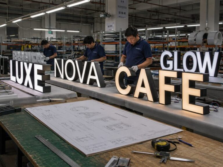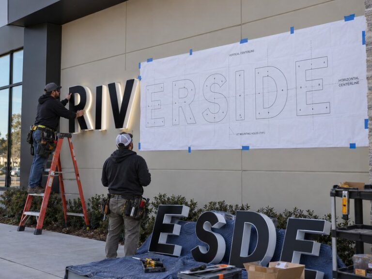

A channel letter sign can look perfect in the design file and still lose much of its impact after installation. The problem usually appears when the letters reach the wall: a cable drops below one character, jumper wires become visible from the side, the power supply has nowhere sensible to go, or the installer discovers there is no usable space behind the façade. At that point, hiding the wiring becomes harder because the real mistake happened much earlier. Clean channel letter wiring is not created by covering cables after installation. It begins by deciding how every letter, wire exit, electrical circuit, mounting point, power supply, wall penetration, and service location will work together before fabrication starts.
The cleanest way to hide wiring behind channel letters is to plan the mounting method, wire exits, low-voltage routing, power-supply location, and service access before production. Flush-mounted letters usually route wires through the façade, while raceways and backboards create concealed wiring space when direct wall access is difficult. Outdoor installations must also protect penetrations from moisture without blocking drainage or future maintenance access.
That distinction matters because a visually clean sign can still be difficult to install or service if the wiring system is poorly planned. Imagine an installer standing on a lift with twenty finished letters, a drilling template, and a storefront scheduled to open the next morning. If nobody decided where those twenty wire exits should meet the electrical system, the problem is no longer cosmetic. It becomes an installation, electrical, scheduling, and possibly waterproofing problem. The best-hidden wiring is usually the wiring that was designed correctly long before anyone started drilling the wall.
How Is Channel Letter Wiring Hidden?

Channel letter wiring is hidden by routing LED leads behind each letter, through the wall, or into a raceway or backboard before they connect to the power system. The power supply is placed in a protected, ventilated, and serviceable location. Good concealment keeps cables out of normal viewing angles while preserving correct voltage, drainage, access, and safe electrical connections.
What Needs to Be Hidden?
A finished channel letter installation may look simple from the street, but the electrical system behind it contains several different elements. Each illuminated letter usually contains LED modules, short internal leads, connections, and an outgoing low-voltage cable. Those letter leads eventually connect to one or more LED power supplies, which then interface with the building electrical system according to the approved project configuration and local installation requirements. Hiding the wiring properly means giving each of these parts a planned location rather than simply pushing wires into whatever empty space happens to be available.
The most important distinction is between concealing wiring and covering wiring. Covering a cable after installation often produces an improvised result because the electrical path was never designed into the product. Proper concealment starts by defining where the cable leaves the letter, where it enters the façade or mounting structure, how multiple circuits are grouped, where the power supply sits, and how a technician will reach the electrical components later. When these details are defined before production, the finished sign can appear visually simple even though the electrical system behind it is carefully organized.
With individually mounted channel letters, the wire exit normally sits behind the body of the character where it cannot be seen from normal front and side viewing positions. Raceway-mounted letters send those leads directly into a shared metal enclosure, while backboards create a larger controlled space behind several letters or a complete logo. The goal is not to make every electrical component permanently inaccessible. Some items, especially power supplies and important connection points, need to remain reachable. A professional system hides the electrical work from the viewer without hiding it from the person who may need to service it in the future.
How Low-Voltage Wiring Is Routed
Most LED channel letter systems use low-voltage DC after the power supply, and 12V and 24V configurations are both common in the sign industry. The selected voltage must match the LED modules, power supply, and overall electrical design. Inside each letter, the LED modules are grouped into circuits and the wiring is secured so it does not rub against metal edges, block drainage, place tension on LED modules, or become trapped when the letter is assembled. Low voltage reduces certain electrical risks, but it does not eliminate the need for proper circuit planning.
Once wiring leaves the letter, the routing depends on the mounting method. Flush-mounted letters usually pass each lead through a penetration directly behind the character into a wall cavity or another concealed area. Raceway-mounted letters route individual leads into the raceway, allowing several circuits to be organized in one shared enclosure. Backboards can create a similar concealed zone between the panel and the architectural wall. In all three cases, the best route is usually short, protected, mechanically secure, and easy to understand during installation and future maintenance.
Cable length also affects electrical performance. Long low-voltage runs create resistance, and resistance creates voltage drop. A sign can still power on while delivering weaker illumination to letters farther from the power source. Conductor size, current, cable length, polarity, circuit grouping, and connection quality all influence the result. This is one reason experienced sign engineers do not treat wiring as a final assembly detail. A sign that lights up during a quick test is not automatically a well-engineered electrical system if its longest runs, connectors, or circuit loads are poorly planned.
Where the Power Supply Goes
The power supply is often the largest electrical component that needs to be concealed, and it should never be treated as something that can simply be pushed into the nearest available cavity. Power supplies generate heat, contain electrical connections, and may need replacement during the service life of the sign. Depending on the project, a driver may be positioned inside a raceway, behind an accessible interior wall area, in a planned enclosure, or in another location that remains protected while still being reachable for inspection.
A good location should normally be dry, reasonably ventilated, protected from accidental damage, and close enough to the letters to avoid unnecessarily long low-voltage runs. The exact solution depends on the sign structure, wall access, environmental exposure, component instructions, and local electrical requirements. Exterior installations require additional attention because a location that appears sheltered may still experience condensation, moisture, heat buildup, or direct weather exposure over time. For this reason, power-supply placement should be confirmed as part of engineering rather than left entirely to field improvisation.
One of the most common mistakes is focusing so heavily on making the installation look clean that the power supply becomes permanently trapped. That can transform a routine driver replacement into a wall-repair project. The more useful question is not simply, “Where can the driver be hidden?” It is, “Where can the driver be hidden while remaining protected, ventilated, and serviceable?” That small change in thinking usually produces a much more practical installation.
| Component | Common Concealed Location | Key Requirement |
| LED module wiring | Inside each letter | Secure routing and correct polarity |
| Letter leads | Behind wall, raceway, or backboard | Planned wire-exit position |
| Low-voltage connections | Protected enclosure or concealed service area | Moisture protection and organization |
| Power supply | Raceway, accessible interior area, or service enclosure | Ventilation and access |
| Outdoor penetrations | Behind sign assembly | Correct sealing and drainage |
| Building electrical feed | Approved site electrical route | Local electrical compliance |
Which Mounting Method Hides Wiring Best?

Flush mounting usually produces the cleanest visual result because the letters appear directly attached to the façade and the wiring disappears behind them. Raceway mounting is often more practical when access behind the wall is limited, while backboards simplify multi-part logos and finished-wall installations. The best choice depends on wall construction, electrical access, appearance, installation time, and service requirements.
Flush Mount
Flush mounting is usually the first option considered when designers want individual letters to appear directly on the building with no obvious supporting enclosure. From the front, this can create the most minimal architectural result because the wall remains visible between the letters. Each character is normally positioned using a template, while its low-voltage lead passes through a concealed penetration behind the body of the letter. If the wall provides a suitable cavity or accessible space, the electrical system can remain almost completely invisible from normal viewing angles.
The visual advantage comes with an important condition: the building must support the installation method. A framed wall with accessible space behind it may be straightforward, while solid concrete, finished stone, insulated panels, glass-adjacent façades, curtain-wall systems, or complicated masonry can make individual hidden wiring more difficult. These surfaces may contain waterproofing membranes, structural members, insulation, existing building services, or decorative finishes that should not be penetrated casually. The cleaner the finished surface, the more expensive drilling mistakes can become.
For that reason, flush mounting should not automatically be treated as the superior choice. It produces an elegant result when the site has been coordinated for it. When the wall is unsuitable, forcing individual flush mounting can increase drilling, installation time, and field risk. In some projects, a carefully designed raceway creates a more professional overall result because it solves the electrical and installation problem cleanly instead of hiding a difficult site condition behind an attractive elevation drawing.
Raceway Mount
A raceway is a metal enclosure installed behind the channel letters. The letters attach to the front of the raceway, while their low-voltage leads enter the enclosure instead of passing separately through the building. This allows several letters, circuits, and compatible electrical components to be organized within one controlled structure. The main advantage is consolidation: a row of individual characters becomes a more integrated installation system rather than a collection of separate mounting and wiring problems.
Raceways are especially useful on existing storefronts, leased properties, masonry façades, locations with poor interior wall access, and projects where the building owner prefers fewer distributed penetrations. They can also shorten field installation because letter spacing and much of the electrical organization are established before the sign reaches the site. This is valuable for chain stores and repeat projects where every hour spent aligning letters or diagnosing field wiring adds labor cost and installation risk.
The main compromise is visual. A raceway remains visible, so its height, depth, finish, access covers, and relationship to the letters matter. A poorly proportioned enclosure can make a high-quality set of letters look temporary or overly industrial. A better raceway is sized only as large as the structure and electrical system require, coordinated with the façade color, and positioned so it remains visually secondary. When properly engineered, the raceway does not look like a box added after the sign was designed. It looks like an intentional part of the sign system.
Backboard Mount
A backboard places several letters or logo elements onto a larger common panel, creating a controlled surface that can also conceal cable routes behind the assembly. This method is particularly useful on finished interior walls, decorative stone, irregular surfaces, reception areas, or projects containing many small logo components that would otherwise require numerous individual mounting and wiring points. Much of the positioning and electrical organization can be completed in the factory before the assembly reaches the site.
The backboard should not be treated as a simple piece of material placed behind the letters. Its overall size, thickness, edge treatment, stiffness, weight, wall spacing, mounting holes, and wire exit all influence the installation. A large panel that is too thin can bow, while a clear acrylic board can reveal cable shadows if wiring is not carefully organized. A metal panel that is unnecessarily thick may add considerable weight without improving the actual performance of the sign.
Visually, a backboard occupies more space than a typical raceway, so it becomes part of the design language. Clear acrylic, painted metal, composite material, or another finish can create very different effects. The best projects use the backboard intentionally, allowing it to simplify wiring and installation while supporting the architecture rather than competing with the logo.
| Mounting Method | Wiring Location | Wall Work | Visual Result | Service Access |
| Flush mount | Behind façade | More distributed | Most minimal | Depends on wall access |
| Raceway mount | Inside raceway | More consolidated | Raceway remains visible | Usually convenient |
| Backboard mount | Behind common panel | Consolidated | Panel becomes part of design | Can be planned into assembly |
How Do Flush-Mounted Letters Hide Wiring?

Flush-mounted letters hide wiring by placing each cable exit behind the character and routing the low-voltage lead through the façade into a concealed area. This method works best when the wall structure, template, wire exits, electrical route, and service access are known before production. Exterior installations also need correct sealing so hidden wiring does not create a path for water.
Wall Penetrations
The basic idea is straightforward: the wall penetration should sit behind the body of the letter where the finished character hides it. The real installation can be much more complicated because architectural walls are rarely simple. A framed drywall system may contain convenient cavities, but studs or other services may block the planned route. Brick may be solid masonry or veneer over a cavity. Concrete can require deeper drilling, while insulated metal panels and cladding systems may include membranes, air gaps, structural clips, and thermal layers that cannot be treated like ordinary walls.
Before drilling, the local installation team should understand what may be located behind the surface, including electrical lines, plumbing, framing, structural members, façade supports, and other building systems. The sign manufacturer can determine where the wire should leave the letter, but the installer and project team must verify what exists inside the actual building. This division of responsibility is important because no factory drawing can reliably reveal concealed services in a wall that has not been surveyed.
Projects are much easier when signage is coordinated before the building finishes are complete. Electrical access, backing, wall penetrations, and service locations can be planned while the construction team still has access to the structure. On completed storefronts, the sign often needs to adapt to the architecture instead. That is where careful site photographs, wall information, and installer feedback can prevent a visually attractive design from turning into an expensive field modification.
Wire Exit Position
A wire exit may look like a minor manufacturing detail, but a poorly placed exit can create significant installation problems. The cable should normally leave the back of the letter in an area completely hidden from normal viewing angles while also avoiding mounting studs, braces, drainage points, and internal LED components. If the wire is too close to the edge, it may become visible from the side. If it is positioned behind structural hardware, installers may struggle to route it through the intended opening.
Complex logos require more attention than simple block letters. Narrow strokes, small enclosed areas, and unusual shapes may offer limited room for both LED modules and convenient cable exits. This is why wire-exit placement should be reviewed during engineering rather than left to a production worker at the final assembly stage. The approved drawing should establish a practical relationship between the internal LED layout, mounting hardware, wall penetration, and expected electrical route.
For repeat-store programs, consistent wire-exit logic becomes especially valuable. The exact position may change as letter sizes change, but the underlying engineering rule can remain similar across multiple locations. That makes installation templates easier to understand, reduces variation between sites, and allows service technicians to work with a more predictable system. Wire exits are almost invisible when they are correct, but they quickly become one of the most noticeable problems when they are wrong.
Halo-Lit Wiring
Halo-lit channel letters make concealment more demanding because the characters intentionally stand away from the wall. A common working stand-off range is approximately 20–50 mm, although the final distance should be selected according to letter size, LED arrangement, wall color, surface texture, and the desired lighting effect. A smaller gap usually creates a tighter halo, while a larger gap can create a broader and softer light spread behind the letter.
The same gap that creates the halo also makes the space behind the letter easier to see from certain angles. A cable that would disappear completely behind a flush-mounted character may become visible when the letter is raised 30 or 40 mm from the wall. The low-voltage lead should therefore travel from the letter toward the wall in a position shielded by the letter body from normal viewing angles. Loose loops are particularly undesirable because rear illumination can make cable shadows more obvious at night.
The wall surface is also part of the optical system. Smooth light-colored walls reflect halo light differently from dark brick, rough stone, timber, or deep-profile cladding. Stand-offs, wires, and mounting hardware may create shadows that are barely visible in daylight but obvious when the LEDs are on. A strong halo-letter installation should therefore be judged from both daytime and nighttime perspectives rather than assuming that hidden wiring in the daytime will remain visually discreet after dark.
Outdoor Sealing
Every exterior wall penetration creates a potential route for water, including cable holes, stud holes, raceway anchors, backboard fasteners, and bracket penetrations. These locations need weather protection using methods and materials suitable for the façade and environmental conditions. The correct approach should consider the wall material, cable jacket, metal surface, expected movement, UV exposure, and the way water may travel across or behind the finished assembly.
Sealing does not mean covering every opening with the maximum possible amount of sealant. Channel letters often include intentional drainage paths, and those paths should remain open. Blocking drain holes, pressing them directly against the wall, or filling internal drainage routes can trap moisture rather than protect the sign. Cable entries should also avoid locations where water naturally collects. Outdoor reliability depends on the relationship between sealing, drainage, connectors, enclosure design, corrosion protection, and installation workmanship.
A carefully manufactured exterior letter can still suffer water problems if the installer leaves the building penetration unsealed or mounts the product in a way that blocks drainage. The reverse is equally true: excellent site sealing cannot correct a poorly designed letter that traps water around electrical connections. The most reliable installations treat the sign and the building interface as one weather-management system instead of assuming that either the factory or the installer can solve every moisture problem independently.
How Do Raceways and Backboards Hide Wiring?

Raceways hide wiring inside a shared metal enclosure, while backboards create concealed space behind a larger mounting panel. Both methods allow multiple letters to use a controlled electrical path rather than routing every cable independently through the wall. They are especially useful when direct wall access is difficult, when fewer penetrations are preferred, or when faster, more repeatable installation is important.
Inside a Raceway
A raceway creates a dedicated zone for electrical and mechanical organization. Each letter sends its wiring directly into the enclosure, where circuits can be grouped, identified, connected, and routed toward the power system. Depending on the approved configuration and applicable requirements, compatible power supplies or related electrical components may also be positioned within the raceway. This makes the enclosure far more than a decorative strip behind the letters; it becomes the principal interface between the fabricated sign and the building.
Internal space needs to be considered carefully. The raceway must allow room for cable routing, connection points, conductor bends, possible power supplies, structural reinforcement, access covers, and weather-management details. If the enclosure is designed only from the front elevation, it may appear attractive on paper but become extremely difficult to wire in the workshop or service later. An enclosure that is unnecessarily large creates visual bulk, while one that is too small can create electrical congestion and poor access.
The access cover is particularly important because one of the strongest practical advantages of a raceway is the ability to reach components without opening the building wall. Long raceways may also need to be divided into sections for transportation or lifting. Section joints should therefore be coordinated with wiring, structural connections, and visual alignment. A good raceway should arrive on site as an organized system rather than a hollow box that still requires extensive electrical problem-solving during installation.
Reducing Wall Work
One reason raceways remain popular in commercial signage is that they can move a large amount of installation work away from the façade and into the controlled factory environment. Consider a sign containing ten or twelve illuminated characters. Individual mounting may require numerous mounting points and electrical penetrations distributed along the storefront. With a raceway, the letters are already aligned on a common structure, and the wiring is largely organized before shipment.
The raceway still requires secure attachment, correct leveling, electrical access, and appropriate weather protection, so it should not be described as requiring only a single hole or virtually no installation work. The real advantage is consolidation. Instead of repeating the same layout and routing process for each letter, installers work with a more integrated assembly. This reduces the number of decisions that need to be made while technicians are on ladders, scaffolds, or lifts.
That difference becomes particularly important in repeat retail programs. A chain opening dozens of locations can lose considerable time if every store uses a different letter-spacing method, electrical path, and field wiring arrangement. A standardized raceway system can make installation more predictable while still allowing size, color, and overall sign length to change. Factory-controlled alignment and electrical organization also make pre-shipment testing more meaningful because the assembly can be illuminated as a complete system rather than as isolated characters.
Backboard Wiring Space
A backboard provides a larger controlled surface behind the logo and can conceal wires while simplifying the relationship between multiple letters and the wall. This is valuable on decorative surfaces where numerous individual penetrations would be risky or visually undesirable. A reception wall finished with stone, timber panels, specialty coatings, or other expensive materials may benefit from a backboard because much of the alignment and wiring can be completed before the assembly reaches the site.
The backboard still requires engineering attention. Overall dimensions, panel thickness, material stiffness, mounting pattern, edge appearance, wall spacing, total weight, wire exit, and service access all influence the final result. A panel that is too thin may distort or bow, while one that is unnecessarily heavy increases handling and structural demands. Transparent or translucent backboards require even more careful cable organization because wires and shadows can become visible through the material.
A useful backboard creates hidden space without visually overwhelming the logo. Its shape and finish should feel deliberate rather than appearing as a convenient panel placed behind the letters at the last minute. In many interior projects, the board can also become a useful design element, particularly when its material or color supports the architecture. The strongest installations balance these visual benefits with the practical advantage of simpler wiring and faster positioning.
Service Access
Raceways and backboards are most valuable when they make the sign easier to maintain as well as easier to install. Raceway access covers can allow technicians to reach drivers, connectors, and circuit wiring without removing the letters or opening the building wall. Backboards can also be designed with removable sections, accessible clearances, or defined service points so that electrical components are not permanently trapped behind finished architectural surfaces.
The opposite approach may create a beautiful first-day installation but a difficult service problem later. If a driver or important connection is buried where it can only be reached by damaging a wall, removing stone panels, or dismantling the complete sign, the design has transferred installation simplicity into future maintenance cost. Commercial signage may remain in place for years, so service strategy should be considered part of the original product engineering.
Circuit organization also matters. When a sign contains multiple power supplies or electrical branches, technicians should be able to determine which letters connect to each circuit without tracing an unmarked bundle of wires. Clear routing, sensible grouping, and retained production records can make troubleshooting significantly faster. Hidden wiring should disappear visually, but it should never disappear from the technical logic of the sign.
How Do You Keep Hidden Wiring Safe?

Hidden channel-letter wiring stays reliable when voltage, conductor size, cable length, current, connection quality, waterproofing, ventilation, and service access are considered together. LED letters commonly use 12V or 24V low-voltage circuits after the power supply, but low voltage still requires careful design. Concealment should never create excessive voltage drop, inaccessible drivers, weak connections, trapped moisture, or uncontrolled wiring.
12V and 24V Systems
Both 12V and 24V systems are widely used for LED channel letters, and neither should be selected purely because one voltage is more familiar. The LED modules, power supplies, wiring arrangement, circuit length, and overall load need to be compatible. Once the system voltage is chosen, all relevant electrical components should follow the same approved configuration rather than being mixed or substituted casually during assembly or installation.
A common misconception is that low voltage makes wiring unimportant. Current still flows through the conductor, connections still create resistance, and poorly selected cable can still produce performance problems. Long wire runs, high current, undersized conductors, loose connectors, or inconsistent polarity may cause dimming, unstable operation, or complete circuit failure. These issues become especially important on large storefront signs where the farthest letter may be several meters from the power location.
The electrical plan should therefore consider the LED operating voltage, total load, number of circuits, approximate run length, conductor selection, polarity, connection method, and power-supply location. A large sign may require multiple circuits or more than one driver rather than one oversized and distant source. The goal is not to minimize electrical components at any cost. The goal is to build circuits that are stable, understandable, appropriately loaded, and practical to service.
Voltage Drop
Voltage drop is one of the most important reasons cable length and conductor size should be reviewed rather than guessed. Every conductor has resistance, and that resistance causes part of the available voltage to be lost as current travels through the wire. The amount of loss depends on factors including current, cable length, conductor resistance, and connection quality. A small interior logo with a driver positioned nearby may present very little difficulty, while a long storefront sign can create much more demanding electrical conditions.
Possible symptoms of excessive voltage drop include weaker illumination at the far end of a circuit, inconsistent brightness between letters, unstable behavior under load, or performance that improves when fewer letters are connected. These problems can be incorrectly blamed on LED quality because the modules themselves may be functioning normally. The real issue may be that the electrical system cannot deliver the required voltage consistently over the chosen cable route.
There is no responsible universal wire-size recommendation for every channel letter project. The correct selection depends on actual current, run length, equipment, installation method, and applicable requirements. Moving a power supply closer to the sign, splitting a long circuit, or selecting a more suitable conductor can often improve performance. Electrical layout should therefore be treated as part of the product design rather than something that is automatically solved once a cable has been connected.
| Electrical Factor | What Changes | Possible Result if Ignored |
| System voltage | 12V or 24V configuration | Incorrect component matching |
| Cable length | Resistance increases with distance | Greater voltage drop |
| Circuit current | Higher load increases voltage loss | Dim or unstable LEDs |
| Conductor size | Affects electrical resistance | Poor performance if undersized |
| Connection quality | Adds resistance when loose or poor | Flicker, heating, or intermittent faults |
| Circuit grouping | Controls load distribution | Difficult troubleshooting or overloaded routes |
Outdoor Connections
Outdoor electrical connections operate in a much harsher environment than the clean appearance of a finished sign suggests. Rain, condensation, thermal cycling, dust, UV exposure, humidity, and wind can all influence the electrical system over time. A connector positioned behind a letter is not automatically protected simply because it cannot be seen from the street. Moisture can travel through wall penetrations, cable routes, seams, or internal cavities and eventually reach electrical components.
Protection therefore needs several layers. Components should suit the intended environment, cable entries need appropriate sealing, connections should be positioned away from locations where water naturally collects, and drainage paths should remain open. Cables should also be mechanically supported so their weight does not pull on connectors. Outdoor sign reliability is created by the relationship between enclosure design, electrical components, sealing, drainage, corrosion protection, and installation workmanship rather than by a single waterproof label.
Site exposure should also influence the specification. A sign installed under a deep canopy experiences different conditions from one mounted on an exposed coastal façade. High humidity, salt, strong UV exposure, and repeated rain can accelerate deterioration. This is why professional outdoor sign development starts with the actual environment rather than assuming that one weatherproof configuration is suitable for every building and every location.
Power-Supply Access
The power supply deserves more planning than almost any other hidden component because it combines electrical function, heat, physical size, and future maintenance. Before fabrication, the project team should know where the driver will be located, how building power reaches it, how the low-voltage wiring reaches the letters, how a technician will access the location, and whether the surrounding environment is appropriate for the equipment.
Raceways can simplify this process because the electrical location remains physically close to the letters. Remote interior locations can also work well when the building provides accessible and suitable service space. The distance from the driver to the sign should still be considered because longer low-voltage runs can influence conductor requirements and voltage performance. It is not enough for a remote location to be convenient for hiding equipment if that convenience creates an unnecessarily difficult electrical route.
The weakest solution is an undocumented power supply hidden inside an inaccessible wall, ceiling, or architectural cavity where nobody can find it later. Commercial signs may operate for many years, and electronic components can eventually require service even when the letters remain structurally sound. The project drawing or installation information should therefore describe the intended electrical arrangement clearly enough that a future technician can understand the system without relying on the memory of the original installer.
What Should Be Confirmed Before Fabrication?

Before channel letters enter production, confirm the wall condition, mounting system, wire exits, operating voltage, power-supply location, electrical access, environment, and service strategy. These decisions affect letter backs, templates, raceways, backboards, wiring, hardware, and packaging. Solving them before fabrication reduces visible cables, installation delays, drilling mistakes, field modifications, and electrical problems after the sign reaches the site.
Site Information
A logo and an overall sign width are rarely enough to engineer a reliable channel-letter installation. A useful project package should include the best available information about the actual installation site. Wall photographs, dimensions, installation height, indoor or outdoor use, wall material, illumination style, destination country, available power, intended mounting method, and access behind the façade can all influence how the sign should be built.
Wall photographs are particularly useful because they reveal details that may never appear in artwork. Cladding joints, windows, stone modules, architectural recesses, columns, nearby lighting, decorative panels, and other features can change mounting and wiring decisions. For halo-lit letters, wall color and texture also affect the lighting result. For raceways, façade color helps determine an appropriate finish. For individual mounting, wall joints or structural patterns can influence practical drilling positions.
The more information that is available before engineering, the fewer assumptions the production team needs to make. This does not mean every project requires a complete architectural survey before a quotation can begin. It means the design should become progressively more precise as the project moves toward production. The final manufacturing configuration should be based on confirmed information rather than expecting installers to solve unknown wall and electrical conditions after the letters arrive.
Mounting Approval
The final mounting method should be confirmed before manufacturing starts because terms such as “wall mounted” are too broad for production. The project should clearly identify whether the letters will be individually flush mounted, stand-off mounted, attached to a raceway, installed on a backboard, or fixed to another engineered structure. Each approach changes the way the letter backs, wire exits, mounting holes, accessories, packaging, and installation templates are prepared.
Halo-lit letters should also include an intended stand-off distance. Approximately 20–50 mm is a common working range, but final spacing should be selected according to the letter dimensions, LED arrangement, wall surface, and approved lighting effect. Raceway projects need confirmed enclosure dimensions, finish, mounting strategy, and access arrangement. Backboards require a defined material, shape, thickness, edge treatment, and relationship with the wall.
The manufacturer can prepare studs, brackets, holes, templates, and sign-side mounting hardware according to the approved project information, but final anchors must suit the actual building surface and local structural requirements. An anchor appropriate for concrete may not be suitable for hollow masonry, framed walls, stone veneer, or curtain-wall systems. Installation therefore remains a coordination point between manufacturing and the local project team rather than something that should be guessed from a generic drawing.
Templates and Wire Exits
The installation template is one of the most useful low-cost components in a channel-letter project because it transfers the approved digital layout onto the physical building. A well-prepared template can establish the baseline, letter spacing, overall position, mounting points, stud locations, and wire exits. This gives the installation team a clear reference instead of requiring the layout to be rebuilt from measurements while technicians are already on site.
Small positioning errors can become surprisingly obvious across an entire word. A single letter installed slightly high or low can disrupt the visual baseline, while inconsistent stand-off distances on halo letters can create different shadow and glow patterns between characters. Wire exits require the same level of coordination. If a wall hole is drilled according to the template but the cable leaves the manufactured letter somewhere else, installers may need to enlarge the opening, alter the product, or expose wiring that was intended to remain hidden.
Templates are particularly valuable for repeat programs because approved mounting logic can be retained even when store dimensions change. The exact letter size may vary, but the relationship between alignment, mounting points, wire exits, and electrical routing can remain systematic. Saving these records also supports future replacement or expansion work because the project does not need to be reconstructed from photographs and installer memory.
Electrical Testing
Illuminated channel letters should be electrically tested before shipment, not for the first time after they are mounted on the building. At a minimum, every illuminated letter should be powered and checked for operation. Inspection should look beyond whether the LEDs simply turn on. Dark areas, visible hotspots, inconsistent color, unusual color temperature, loose wiring, poor connections, unstable drivers, control issues, and intermittent behavior can all indicate problems that are easier to correct in the factory.
For iduoduo illuminated-sign production, the established process includes 100% illumination inspection and a 72-hour pre-shipment powered test. The value of this process is practical. A short bench test may not reveal an unstable connection or early component problem that appears after extended operation. Running the system for a longer period gives the production and quality teams more opportunity to identify abnormal behavior while the product is still in a controlled manufacturing environment.
A 72-hour test should not be interpreted as a promise that an electrical product can never develop a fault. No responsible sign manufacturer can guarantee that. Its purpose is to reduce avoidable early failures before international shipment and installation. Correcting a wiring or power-supply issue on a workbench is far easier than diagnosing the same problem after the letters have been packed, transported, installed several meters above ground, and connected to a completed storefront.
| Item | Confirm Before Fabrication | Check Before Shipment |
| Mounting method | Flush, raceway, backboard, or stand-off approved | Hardware and mounting points checked |
| Wire exits | Position coordinated with layout | Actual exits inspected |
| Voltage | LED system and site requirements confirmed | Power supply and LEDs verified |
| Power location | Serviceable location planned | Electrical components checked |
| Halo spacing | Stand-off distance approved | Stand-offs checked for consistency |
| Outdoor protection | Sealing and drainage strategy defined | Entries and drainage inspected |
| Template | Final layout approved | Template matched to product |
| Illumination | Lighting requirements approved | 100% illumination inspection |
| Powered testing | Testing requirement defined | 72-hour test for iduoduo illuminated products |
The best time to solve channel-letter wiring is before the letters exist. When wall conditions, mounting style, wire exits, electrical routes, power-supply positions, and service access are decided together, the finished installation becomes more predictable for everyone involved. The letters look cleaner, installers spend less time improvising, and future maintenance becomes easier because the system still has a clear technical logic behind the finished façade.
For projects being developed with iduoduo, early information such as the logo file, overall dimensions, wall photographs, illumination style, indoor or outdoor environment, destination market, voltage, preferred mounting method, and known site restrictions can be reviewed before production begins. That allows the wiring, mounting interface, raceway or backboard option, and power arrangement to be considered as part of the product instead of becoming problems discovered after shipment.
Ultimately, good concealed wiring is not measured by how cleverly somebody manages to hide a cable at the end of the job. It is measured by whether the sign was designed so that the cable always had the right place to go. When electrical planning, manufacturing, wall conditions, and installation strategy are treated as one system, viewers notice the letters, logo, and light rather than the technical work that makes them possible.
Frequently Asked Questions
How do you hide wires for individual channel letters?
The most common method is to position the wire exit behind each letter and route the low-voltage lead through a matching wall penetration into a concealed cavity or accessible electrical area. The letter body hides the penetration from normal viewing angles. This approach works best when wall construction and interior access are understood before fabrication because solid concrete, stone, cladding systems, or inaccessible finished walls can make individual concealed routing much more difficult.
Do channel letters need a raceway?
No. Channel letters can be individually mounted without a raceway when the building allows appropriate mounting and hidden wiring. A raceway becomes useful when interior wall access is poor, fewer distributed penetrations are preferred, or faster installation is important. It can consolidate multiple letters, circuits, and compatible electrical components into one enclosure. Whether a raceway is better depends on the wall, visual requirements, service strategy, property restrictions, and installation conditions.
Is flush mounting better than raceway mounting?
Neither method is universally better. Flush mounting usually provides the cleanest architectural appearance because no common enclosure is visible between the letters, but it can require more individual penetrations and better access behind the façade. Raceway mounting may simplify installation, wiring, and future service on existing buildings. The stronger solution is the method that fits the actual wall and electrical conditions rather than the one that looks cleaner in an isolated product photograph.
Where should a channel letter power supply be installed?
A channel-letter power supply should normally be placed in a protected, reasonably ventilated, and serviceable location that suits the equipment and project requirements. Depending on the design, this may be inside a suitable raceway, within an accessible interior area, or in another approved enclosure. The distance to the letters matters because long low-voltage runs can increase voltage drop. A driver should not be permanently buried where future replacement requires damaging the building.
How far should halo-lit channel letters stand off the wall?
A common working range is approximately 20–50 mm, although the correct distance depends on letter size, LED arrangement, wall color, wall texture, and the intended halo effect. Smaller gaps often create a tighter, more concentrated halo, while larger gaps usually produce a wider and softer spread. Stand-off distance also affects cable visibility and shadows, so the wiring path should be evaluated together with the lighting effect rather than as a separate detail.
How can voltage drop affect LED channel letters?
Voltage drop occurs because conductors have electrical resistance. As cable length or current increases, more voltage can be lost before it reaches the LEDs. Excessive drop may cause weaker illumination, uneven brightness, or unstable operation, especially on long storefront signs. Proper conductor selection, suitable circuit grouping, sensible power-supply placement, and shorter low-voltage runs can help control the problem. The correct design should be based on the actual electrical load rather than a universal wire-size rule.