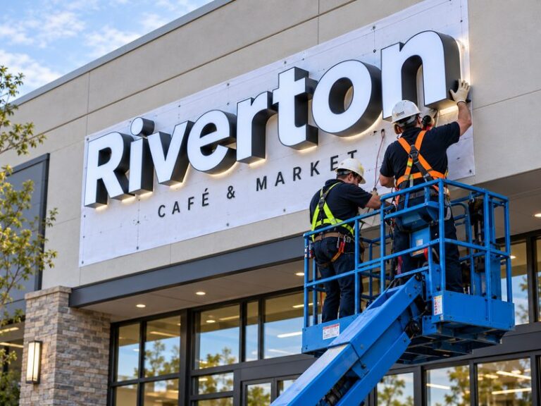

Individually mounted channel letters can create one of the cleanest storefront appearances because each letter seems to sit directly on the building rather than being carried by a visible raceway or common cabinet. The finished result looks simple, but the installation process is not. Every letter has its own mounting position, fasteners, wire exit, spacing relationship, and alignment requirement. On an illuminated sign, those details also have to work with the power supply, low-voltage wiring, weather sealing, drainage, and future maintenance. A small positioning error on one letter may be hard to notice up close, yet become obvious once the entire wordmark is viewed from across the street.
Individually mounted channel letters are installed by transferring the approved layout to the façade with an accurate template, confirming the wall structure and power plan, drilling the required mounting and wire holes, fixing each letter separately, connecting the electrical system, sealing penetrations, and checking the complete sign for alignment, illumination, spacing, and weather protection before final acceptance.
The most important lesson is that installation begins before anyone drills the first hole. Imagine receiving a beautifully finished set of letters only to discover that the template was printed at the wrong scale, the wall contains no suitable backing where the studs land, or the power supply has nowhere accessible to go. The letters may be perfect, yet the project is already in trouble. Good installation is therefore a coordinated process between design, manufacturing, site conditions, and local installation work.
What Are Individually Mounted Channel Letters?

Individually mounted channel letters are installed one letter or logo element at a time instead of being fixed to one common raceway or backboard. This creates a cleaner architectural appearance, but it also increases the importance of accurate templates, individual mounting points, wire exits, wall preparation, power routing, spacing, waterproofing, and future service access.
Individual Mounting Basics
An individually mounted sign is produced as one complete visual composition but installed as a series of separate physical components. Each letter may have its own threaded studs, fixing holes, spacers, stand-offs, low-voltage wire exit, or another mounting feature designed into the rear of the product. Once the letters are taken out of the packaging, their visual relationship is no longer controlled by a shared metal cabinet, so the installer must recreate the approved layout precisely on the building.
That is why the installation template is so important. It usually defines the overall sign width, letter positions, centerline, hole locations, stud positions, wire exits, and orientation. The template transfers the geometry of the approved drawing to the real façade and helps keep each element in the correct place. It should never be treated as a rough guide or as something that can be adjusted casually once drilling has started.
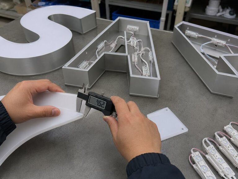
Channel letters themselves are also more complex than they appear from the front. A typical illuminated letter can include a face, metal return, rear panel, LED modules, internal wiring, power connections, drainage features, mounting structure, and site interface. iduoduo’s Channel Letter engineering documentation treats mounting structures, wiring, weather protection, drainage, and installation interfaces as part of the product rather than as separate afterthoughts.
The practical implication is simple: mounting method, wire exit, wall condition, power location, and maintenance access should be discussed before production begins. When those details are left until installation day, the installer may be forced to modify a finished product or make unnecessary changes to the building.
Direct, Flush, and Stud Mount
Direct mount, flush mount, and stud mount are often used in similar conversations, but they do not always describe exactly the same thing. Flush mounting usually describes the visual relationship between the product and the wall, meaning that the letter sits close to the façade. Stud mounting describes the mechanical method more specifically, with threaded studs or rods projecting from the rear of the letter and fitting into corresponding holes in the wall.
The two can overlap. A front-lit letter may be stud mounted while sitting visually close to the wall. A halo-lit letter may also use studs, but it normally needs controlled stand-off spacing so the rear light can spread across the wall. In iduoduo’s installation documentation, flush mounting requires attention to wall flatness, rear clearance, wiring, waterproofing, and service access, while stud mounting requires control of stud length, diameter, wall condition, template accuracy, and spacing from the wall.
For halo-lit applications, the technical material records a common stand-off range of about 20 to 50 mm, with the final distance depending on letter height, LED arrangement, wall material, wall color, and the approved visual effect. This is a useful industry reference, but it should not be treated as a universal rule because different products and façades can require different spacing.
The safest approach is to avoid relying only on mounting terminology. A production drawing should show the actual rear construction, fixing method, stand-off distance where required, wire exit, and expected power arrangement. Those details are more useful to an installer than a label such as “direct mount” on its own.
Individual Mount vs Raceway Mount
The main difference between individual mounting and raceway mounting is the number of interfaces between the sign and the building. With individually mounted letters, each letter is positioned directly against or close to the façade, which can mean multiple fixing points and multiple wire penetrations. The advantage is a cleaner appearance because there is no large metal enclosure behind the letters.
A raceway changes that relationship. Multiple letters are mounted onto a common metal enclosure, and the enclosure becomes the main component attached to the building. Wiring and, in many cases, power-related components can be organized inside the raceway. This can reduce the number of façade penetrations and simplify installation when the wall is difficult to access or when the property owner wants fewer holes.
iduoduo’s installation documentation notes that raceways can reduce building penetrations, centralize wiring and power components, speed installation, and simplify removal in suitable projects. Those advantages can be especially useful for leased properties, remodels, or projects where the interior side of the wall is difficult to reach.
| Installation Method | Visual Result | Wall Interface | Wiring Approach | Common Project Consideration |
| Individually mounted | Clean façade with no common cabinet | Multiple individual fixing points | Concealed or separately routed | Requires accurate template and site preparation |
| Flush mounted | Letters sit close to wall | Individual studs or fixing holes | Usually concealed | Wall flatness and sealing are important |
| Stud mounted | Hardware mostly hidden | Stud holes in substrate | Depends on lighting type | Stud position and hole tolerance must match |
| Raceway mounted | Raceway remains visible | Fewer main fixing zones | Wiring centralized in raceway | Installation can be faster |
| Backboard mounted | Unified panel behind letters | Backboard becomes main interface | Wiring can be organized behind panel | Useful on difficult or finished walls |
The correct mounting method depends on the building, brand appearance, lease restrictions, wall construction, maintenance plan, electrical layout, access, and local requirements. Individual mounting should be chosen because it suits the project, not simply because it looks more elegant in a rendering.
What Should You Check Before Installation?

Before installation, confirm the final site dimensions, centerline, wall type, structural backing, power location, hidden services, template scale, access equipment, mounting method, and local responsibilities. The visible wall finish does not always provide structural support, so installation decisions should be based on the complete wall assembly rather than only on what can be seen from the outside.
Site Dimensions
A drawing may be approved weeks or months before the sign is installed, and buildings often change during that period. Cladding joints can move, doors can become wider, ceilings can shift, electrical points can be relocated, or another tenant sign may appear nearby. For that reason, a final site survey should be treated as a separate step instead of assuming that the original measurements are still exact.
The installer should confirm the available wall width and height, proposed sign centerline, vertical position, door and window openings, canopy edges, façade joints, gutters, lighting fixtures, neighboring signs, access panels, and any other features that could affect the finished sign. Overall sign width should then be compared with the real installation area. A logo may technically fit on a wall but still look crowded if there is not enough breathing space around it.
The installation team should also confirm how the letters and equipment will physically reach the façade. Larger projects may require a boom lift, scissor lift, scaffold, crane, or several installers working together. The working area should be checked for traffic, landscaping, overhead services, canopies, restricted operating hours, and other access limitations that could slow the installation.
The source documentation specifically calls for rechecking wall dimensions, installation center, doors, windows, façade divisions, power, hidden services, framing, obstacles, transport routes, lifting equipment, and installation time restrictions before work begins.
Wall Construction
The visible façade is not always the structure that should carry the sign. A metal panel may only be a decorative skin over structural rails. Stone may be a thin cladding layer over a cavity. EIFS can contain insulation that cannot safely carry a heavy sign by itself. Drywall may have structural studs only at certain positions, while a glass façade may not allow drilling at all.
For this reason, the key question is not simply “What material is the wall?” but “What is behind the visible surface, and where is the reliable structural support?” The answer determines the type of anchor, drilling depth, fixing pattern, and whether additional backing or brackets are required.
The installation standard identifies concrete, solid brick, hollow brick, stone, wood finishes, glass, metal curtain walls, ACP, EIFS, drywall, lightweight partitions, plant walls, fabric displays, and temporary structures as different site conditions. It also warns that the surface material may not be capable of carrying the load on its own.
| Wall Type | Main Risk | What Should Be Confirmed |
| Concrete | Incorrect anchor or depth | Concrete condition, drilling depth, hidden services |
| Solid brick | Cracking near edges or weak joints | Brick condition, anchor zone, mortar quality |
| Hollow brick | Low pull-out strength | Cavity construction and suitable fixing system |
| Stone | Surface cracking | Thickness, backing, edge clearance |
| Metal cladding | Thin decorative face | Structural rail or support behind panel |
| EIFS | Compression of insulation | Through-fixing to reliable backing |
| Drywall | Limited surface strength | Studs, blocking, or reinforced substrate |
| Glass | Restricted drilling | Glass type, thickness, frame, approved method |
Installation height also changes the risk profile. A small interior reception logo installed at eye level does not face the same conditions as a large exterior sign several stories above the ground. Outdoor projects may also need local structural review for wind exposure, building movement, and other site-specific factors.
Power and Site Access
Individually mounted illuminated letters require careful power planning because the wiring has to disappear somewhere. Before the template is fixed to the façade, the installer should know where the low-voltage wires will enter the building, how they will be grouped, where the power supplies will be located, and how those power supplies can be accessed later for maintenance.
Power supplies should not be permanently buried inside an inaccessible wall or ceiling if they may need to be serviced in the future. A clean installation should still allow a technician to reach the electrical components without damaging the building finish. The source documentation calls for confirmation of input voltage, power-supply quantity, location, switching, timers, dimming, control methods, maintenance space, and whether final connection will be hardwired by a qualified electrician.
Access equipment should be planned at the same time. If the installer needs a lift, scaffold, or crane, there must be enough space to position that equipment safely. Exterior jobs may also need temporary traffic control, pedestrian barriers, weather monitoring, or coordination with property management.
A good installation plan resolves both the electrical route and the physical working route before the sign arrives. Otherwise, even a fully completed sign can sit in its packaging while the team waits for access, power preparation, or building approval.
Drilling Conditions
Drilling is the moment when planning mistakes turn into permanent damage, so it should never be the first step in the installation process. Before any hole is made, the installer should verify that the template scale is correct, confirm that the layout matches the finished letters, check orientation, identify hidden services, and make sure the proposed hole locations do not conflict with façade joints or structural elements.
The source material specifically calls for checking concealed electrical lines, water pipes, framing, curtain-wall structure, stone joints, glass, power positions, templates, studs, and anchor depth before drilling. These checks are especially important on renovated buildings where original drawings may not reflect later changes.
Hole size and tolerance also matter. A hole that is almost exactly the same diameter as the stud leaves very little room for site variation. A hole that is unnecessarily large makes alignment harder and may require too much sealant. Exterior cable penetrations should be large enough to accommodate the intended cable and protection method, but not so large that weather sealing becomes difficult.
The installer should know the purpose of every hole, what lies behind it, how deep it needs to be, what fixing will go into it, and how it will be sealed before drilling begins.
Which Mounting Hardware Should You Use?

Mounting hardware should match the sign weight, wall construction, fixing depth, installation height, environmental exposure, and local structural requirements. There is no universal anchor for individually mounted channel letters. The manufacturer can provide studs, holes, brackets, templates, and standard hardware, but the final fixing system should be verified against the actual building by the local installation team.
Anchors and Substrates
Anchor selection begins with the substrate, not with the hardware that happened to arrive in the package. Concrete may accept several types of mechanical or chemical anchors depending on the load and edge distance. Solid brick may support suitable masonry fixings, while hollow masonry may require cavity-specific hardware, through-bolts, or a connection to stronger backing.
Timber-backed walls can use properly sized screws where structural wood is confirmed, while steel framing or metal rails may need self-drilling screws, bolts, or engineered brackets. EIFS and insulated wall systems often require a fixing that passes through the soft surface layer and connects to reliable backing without crushing the insulation.
The installation documentation lists several anchor categories, including expansion anchors, chemical anchors, wall plugs, wood screws, self-drilling screws, through-bolts, hollow-wall anchors, specialist façade connectors, and project-specific brackets. It also states that final anchor selection should be made by the local installer or structural professional.
This is an important distinction in international projects. The sign factory can engineer the rear mounting interface accurately, but the installer on site is the person who can inspect the real wall and confirm whether the selected fixing is appropriate.
Stud Size and Position
Stud mounting is common because it keeps most mechanical hardware hidden behind the letters. The studs can be welded, threaded, or otherwise integrated into the rear structure depending on the product design. Their diameter, length, quantity, and position should be matched to the letter size, shape, mounting surface, and required stand-off distance.
Large letters or long horizontal strokes may need more mounting points than small compact characters. Stud positions should also avoid interfering with LED modules, wire exits, drainage features, internal supports, or serviceable parts inside the letter.
The installation template must match the finished stud positions accurately. If the template comes from an early drawing and the stud layout changes during manufacturing, the installer may discover the mismatch only after drilling. That is one reason production files and installation templates should be based on the same approved version.
The technical documentation emphasizes matching stud holes with stud diameter, stud length, wall construction, adhesive where applicable, template position, stand-off distance, and installation tolerance. It also notes that holes that are too tight can make installation difficult, while holes that are too loose reduce positioning accuracy.
Halo-Lit Stand-Offs
Halo-lit letters need a controlled gap between the rear of the letter and the wall because the wall acts as the reflecting surface for the rear illumination. If the letters are pressed directly against the façade, the halo may be weak, uneven, or partially blocked. If the spacing varies from one letter to another, the light effect can also change across the logo.
The source documentation records a commonly used halo-lit stand-off range of approximately 20 to 50 mm, while making clear that the final distance depends on letter height, LED layout, wall surface, and approved visual effect. A smaller gap tends to create a tighter halo closer to the letter edge, while a larger gap usually creates a broader and softer spread.
Wall color and texture are equally important. A smooth white wall normally reflects more light than rough brick, dark stone, or brushed metal. Two signs using the same stand-off dimension can therefore look quite different on different buildings.
Consistency is the priority. If one letter sits 22 mm from the wall and another sits 35 mm away, the variation can become visible after dark even when the daytime installation looks acceptable.
Local Responsibility
Commercial sign projects work best when the responsibilities of the manufacturer and installer are clearly separated. The manufacturer understands the product: dimensions, materials, weight, mounting points, studs, brackets, wire exits, power configuration, and packaging. The local installer understands the site: wall condition, access, structural support, final anchors, local electrical requirements, waterproofing details, and permitting.
iduoduo’s installation documentation reflects this division. The factory can prepare mounting interfaces, holes, studs, brackets, raceways, backboards, templates, wire exits, power supplies, controllers, accessories, installation information, and remote product support. The local team remains responsible for final site measurement, wall condition, anchor selection, structural support, high-level work, electrical construction, wall penetrations, waterproofing, permits, and final acceptance.
This approach is especially important for high-rise façades, curtain walls, large outdoor signs, and projects in areas with significant wind exposure. A responsible manufacturer should make the product interface as clear and repeatable as possible while avoiding assumptions about structural conditions that can only be verified on site.
How Do You Install Each Channel Letter?

Each channel letter should be installed by accurately transferring the approved layout to the wall, confirming all mounting and wire positions, drilling only after the site has been checked, fixing each letter without distortion, and repeatedly checking alignment and spacing. The goal is not merely to install individual letters securely, but to recreate one complete logo exactly as it was approved.
Template Positioning
The installation template is the main reference for transferring the drawing to the building. Begin by locating the approved horizontal centerline and vertical position. Do not automatically use a roofline, cladding joint, floor line, window edge, or other architectural feature as a reference unless it has been verified to be level and included in the approved layout.
Position the template temporarily before marking any holes. Check the overall width, edge clearances, relationship to architectural features, and the position of any logo symbol or secondary text. Then step back far enough to view the sign from a normal pedestrian or vehicle distance. A layout can be dimensionally correct but still look visually unbalanced on the real building.
The source documentation describes installation templates as tools for locating product positions, letter spacing, mounting holes, studs, wire exits, horizontal reference lines, and storefront centerlines. It also notes that templates should identify the product, direction, total width, scale, joints where relevant, and wire exits.
A template reduces positioning errors, but it does not replace final site verification. The installer should still confirm that the printed layout matches the finished product and the actual façade.
Drilling and Mounting
Once the template has been positioned and checked, the mounting holes and wire exits can be marked. Before drilling, it is useful to compare one or two finished letters against the pattern. This simple check can reveal a reversed template, outdated drawing, incorrect print scale, or production change before the building is damaged.
The drilling technique should match the wall material. Concrete, masonry, steel, stone, timber, tile, and insulated façades all require different tools and methods. The installer should also control drilling depth so that the fixing reaches the intended substrate without damaging hidden services.
When fitting each letter, do not force studs into badly aligned holes. Excessive pressure can bend the back of the letter, damage welded studs, crack acrylic components, or distort the stand-off spacing. If a letter does not fit naturally, the cause should be checked before applying force.
Finished surfaces should be protected during installation. Painted metal, polished stainless steel, trim, and acrylic faces can all be scratched by tools, lifts, fasteners, or rough handling. Protective film can remain on the product during much of the mechanical installation as long as it does not become trapped under permanent hardware.
Spacing and Alignment
Spacing is one of the most visible risks in individually mounted channel letters because the final logo is created by the position of every separate component. Each letter can be perfectly level and still produce a poor result if the spaces between letters are wrong or if the whole line drifts upward or downward across the façade.
Installers should follow the approved layout instead of applying one equal numerical gap between every character. Professional typography often uses optical spacing, which means the visual gap between different letter shapes is intentionally different. The space between an A and V, for example, may not match the gap between two vertical characters, even though both look balanced to the eye.
A practical inspection routine is to check the individual letter, then check the relationship to the neighboring letter, and finally step back to review the complete wordmark. The technical documentation makes the same point: individual letters may each be level while the finished sign still looks incorrect because of letter spacing, line spacing, icon relationships, multilingual arrangement, or baseline errors.
The public sees one brand name, not a series of mounting points, so the complete visual result should always guide final adjustment.
Front-Lit and Halo-Lit Differences
Front-lit and halo-lit letters should not be installed exactly the same way because their lighting systems interact differently with the wall. A front-lit letter directs most of its light through the face, so rear spacing mainly affects wiring, drainage, mounting hardware, and access. The visual appearance is less dependent on the exact distance between the letter and the wall.
Halo-lit letters are different because the wall becomes part of the optical system. Rear LED light reflects from the surface and creates a glow around the letter. Stand-off distance, wall color, wall texture, wall flatness, and hidden wiring all affect how that halo looks after dark.
The source documentation requires halo-lit installations to control stand-off consistency, wall color, support height, hidden wiring, halo continuity, letter level, wall flatness, and prevention of local areas touching the wall.
This is why mechanical accuracy becomes part of the lighting quality. A halo-lit letter can be firmly attached and still look wrong if one side sits closer to the wall than the other. Nighttime inspection is therefore essential before the installation is accepted.
How Do You Wire and Seal the Letters?

Individually mounted illuminated letters should be wired according to the specified system voltage, cable length, circuit grouping, polarity, voltage drop, power-supply capacity, and site conditions. Power supplies should remain accessible, outdoor penetrations must be sealed correctly, connectors should be protected from moisture, and designed drainage paths must stay open rather than being blocked by excessive sealant.
Low-Voltage Wiring
Many LED channel-letter systems use 12V or 24V DC, depending on the LED modules, power supply, sign design, and project requirements. The correct voltage should always be confirmed from the product documentation before connection. iduoduo’s electrical guidance covers 12V and 24V configurations and considers wiring length, voltage drop, control requirements, installation environment, and destination market.
Low-voltage wiring still needs proper engineering. Long cable runs can create voltage drop, which may reduce brightness or cause different parts of the sign to perform unevenly. Cable size, route length, circuit grouping, and power-supply location should therefore be reviewed together rather than decided separately.
Polarity must remain correct, connectors should be mechanically secure, and wires should not be trapped between a metal letter and the wall. Larger signs should use clearly labeled circuit groups so installers and service technicians can quickly understand which letters are connected to each power supply.
The installation documentation calls for control of voltage matching, polarity, cable size, length, voltage drop, connectors, grouping, waterproofing, wire support, and circuit identification.
Power Supplies
Power supplies should be selected according to the actual electrical load and installation conditions rather than simply because they can make the sign turn on during a quick test. The installer should verify input voltage, output voltage, total connected load, circuit grouping, cable distance, ventilation, environmental exposure, and any dimming or control equipment.
Power supplies should remain accessible for future maintenance. Installing one behind a permanently sealed wall may create a clean appearance on the first day, but it can turn a simple replacement into a costly repair later. Outdoor or damp locations also require suitable environmental protection and installation methods.
The source documentation emphasizes that power supplies should be located in dry, ventilated, serviceable areas that do not collect water, do not remain under unnecessary long-term exposure, and are not permanently enclosed where they cannot be accessed.
| Electrical Item | Practical Check | Why It Matters |
| LED system voltage | Confirm 12V or 24V | Incorrect voltage can damage components |
| Input voltage | Match local supply to power-supply label | Prevents power-supply failure |
| Cable length | Review longer low-voltage runs | Helps control voltage drop |
| Circuit grouping | Identify letters on each supply | Simplifies troubleshooting |
| Power-supply access | Keep serviceable after installation | Allows future replacement |
| Connector protection | Protect outdoor joints from moisture | Reduces corrosion and faults |
| Grounding | Follow equipment and local requirements | Safety and compliance |
| Final operation test | Energize all circuits | Verifies the complete installed system |
The objective is not simply to create light. A professional electrical layout should remain stable, understandable, and serviceable throughout the normal life of the sign.
Wall Penetrations
Every exterior hole becomes part of the building envelope. Stud holes, cable penetrations, brackets, raceway fixings, and backboard fixings can all become water-entry points if they are not sealed correctly. The sealant or waterproofing method should be compatible with the wall material, cable jacket, metal components, and expected weather exposure.
The source documentation specifically calls for waterproof treatment around stud holes, wire penetrations, raceway holes, backboard holes, bracket holes, curtain-wall penetrations, and building waterproof layers.
More sealant does not automatically mean better waterproofing. Channel letters may include drainage features that allow incidental moisture to escape. Blocking those paths with sealant can trap water inside the product and create problems that did not exist before installation.
The installer should understand the difference between unwanted penetrations that need to be sealed and designed drainage openings that need to remain clear. After installation, every hole should be checked visually rather than assuming waterproofing is complete simply because sealant was applied.
Outdoor Connections
Outdoor electrical connections should be protected against rain, condensation, corrosion, pulling forces, and movement. Connectors need to be properly locked and insulated, supported so that cable weight does not pull directly on the connection, and positioned away from places where water can collect.
The installation standard also describes using a downward drip path where appropriate. Allowing the cable to dip below the entry point can reduce the chance of water naturally following the cable into the building or sign.
Drainage holes must remain open and correctly oriented. They should not face upward, be pressed directly against the wall, be covered with sealant, or be blocked by wiring. These details can seem minor when the installation crew is trying to finish the project, but they can determine whether the sign remains dry after repeated rain cycles.
Good outdoor installation is not about making every part airtight. It is about controlling where water can enter, where it cannot enter, and how any incidental moisture can leave safely.
How Do You Test the Finished Installation?

A finished channel-letter installation should be inspected as one complete mechanical, electrical, optical, and visual system. Check position, overall level, spacing, mounting stability, stand-off distance, illumination, color, wiring, power supplies, waterproofing, drainage, surface condition, and maintenance access before removing access equipment or closing the project.
Alignment and Appearance
The final visual inspection should begin from a distance rather than directly in front of the letters. Stand where pedestrians, customers, or drivers will normally see the sign and evaluate the complete logo. Confirm that it looks centered, balanced, level, and consistent with the approved drawing.
Then move closer and inspect the details. Check overall width, baseline, vertical alignment, letter spacing, line spacing, logo-to-text relationships, stand-off distance, visible fasteners, scratches, remaining protective film, sealant marks, and the relationship between the sign and nearby architectural features.
The technical documentation requires final checks covering product position, horizontal and vertical alignment, letter spacing, line spacing, logo proportion, joints, screws, adhesive marks, protective film, surfaces, wiring, and brackets.
Photographs from several viewpoints are useful because they create a permanent record and can reveal small alignment problems that are difficult to notice while working from a lift. They also provide useful feedback for repeat-store projects where similar signs may be installed at multiple locations.
Lighting Performance
After mechanical installation is complete, energize the full sign and check every letter. Look for flicker, wrong color, major brightness differences, dark areas, hotspots, disconnected sections, controller problems, or signs that a circuit is overloaded.
Front-lit letters should be viewed from the normal viewing distance because very small face variations that are visible from close range may disappear in normal use, while larger dark areas remain obvious. Halo-lit letters should be checked for consistent halo width and brightness around the characters. Uneven stand-off distances, rough wall surfaces, dark wall colors, or local contact between a letter and the wall can create visible differences.
iduoduo performs 100% lighting inspection and 72-hour pre-shipment testing on illuminated products, covering power stability, wiring, LEDs, controls, flicker, temperature rise, brightness, and color before dispatch.
Site testing is still necessary because installation adds new variables, including field wiring, connectors, local power, handling, wall conditions, and final control settings. Factory testing verifies the product, while commissioning verifies the complete installed system.
Waterproofing and Structure
After the sign has been energized and checked visually, the mechanical and weather-protection details should be inspected again. Confirm that studs and fasteners are secure, letters do not move, stand-offs remain consistent, brackets have not distorted, and excessive tightening has not deformed the product.
Outdoor installations should receive a second review of cable holes, stud penetrations, brackets, cladding joints, sealant transitions, connectors, and drainage paths. Maintenance access should also be checked at this stage. A sign may look perfect yet create unnecessary service problems if a power supply cannot be reached or a letter cannot be removed without damaging the façade.
Large outdoor projects may require local structural inspection where wind loading, high installation, curtain walls, complex brackets, or special anchors are involved. The manufacturer can provide dimensions, product weight, materials, mounting plates, hole positions, and production drawings, while the final structural approval should remain with the appropriate local professional.
A finished installation is only complete when both the sign and the building interface have been checked.
Final Records
Installation records become valuable the first time a sign needs maintenance, troubleshooting, or replacement parts. At minimum, keep photographs of the complete finished sign, close-up images of representative mounting conditions, power-supply locations, wiring groups, controller settings where relevant, product labels, and any changes made during installation.
For repeat projects, it is also useful to keep the approved artwork, production drawing, template, mounting-hole layout, wire exits, color information, power configuration, and final site images. If one letter fails later, these records can help a technician identify the correct circuit and power supply quickly. If a replacement letter is needed, the manufacturer can reproduce the original size, mounting interface, wire exit, and finish more accurately.
The source documentation identifies final drawings, materials, LED information, power supplies, mounting holes, wire exits, templates, packaging, and QC records as useful information for repeat production and after-sales troubleshooting.
Good records turn a one-time installation into a maintainable signage system instead of leaving future technicians to reconstruct the project from memory.
Final Thoughts
Individually mounted channel letters are popular because the finished storefront can look clean, precise, and integrated with the building. That visual simplicity is achieved through careful technical work behind the scenes. The template must match the product, the wall must support the chosen fixing system, wire exits must align with the building, power supplies must remain accessible, exterior penetrations must be sealed, and each letter must return to the exact position shown in the approved layout.
The most reliable installations are planned as a connected process from design through manufacturing and final site work. When the manufacturer knows the wall type, mounting preference, installation surface, electrical conditions, and destination market before production, mounting holes, studs, wire exits, templates, power configuration, and packing can all be prepared with the real installation in mind.
For custom Channel Letter projects, iduoduo can prepare the product-side installation interface around the approved artwork, dimensions, lighting method, mounting approach, wire exits, electrical configuration, and template. The local installation team then verifies the real building, selects the final anchors, completes the site electrical work, and performs final waterproofing and acceptance. That division of responsibilities helps reduce the most common installation problems without trying to replace the judgment of professionals who are physically on site.
Frequently Asked Questions
How are individually mounted channel letters attached to a wall?
Individually mounted channel letters are usually fixed using studs, screws, brackets, stand-offs, or another product-specific mounting system. A full-size template transfers the approved letter positions, mounting holes, and wire exits to the façade. The final anchors depend on the wall construction, product weight, installation height, and local requirements. The visible wall finish should not automatically be assumed to provide sufficient structural support, especially on EIFS, metal cladding, drywall, hollow masonry, or stone veneer.
Do individually mounted channel letters need a mounting template?
A mounting template is strongly recommended because it controls the overall sign position, letter spacing, centerline, stud holes, wire exits, and relationships between letters and logo elements. Without a reliable template, installers may level each individual character correctly while still creating inconsistent spacing across the complete wordmark. The template should be checked against the finished product and actual site before drilling because it reduces layout errors but cannot replace a final site survey.
What is the difference between direct mount and raceway mount channel letters?
Direct or individually mounted letters are fixed separately to the building, producing a cleaner façade without a large shared cabinet. Raceway-mounted letters are attached to a common metal enclosure that is then fixed to the building. A raceway can reduce the number of wall penetrations, centralize wiring and power components, and speed installation. Direct mounting usually provides a more integrated architectural appearance but requires more accurate drilling, wiring coordination, and access behind the wall.
How far should halo-lit channel letters stand off from the wall?
A common stand-off range for halo-lit letters is approximately 20 to 50 mm, although the final dimension depends on letter size, LED layout, wall color, wall texture, and the desired halo effect. Smaller gaps normally produce a tighter glow, while larger gaps often create a wider, softer halo. Consistency is more important than selecting one universal dimension, because uneven spacing between individual letters can make the halo brightness and width look noticeably different after dark.
Can channel letters be installed on EIFS or metal cladding?
They can be installed on these façade types, but the visible surface should not automatically be treated as the load-bearing structure. EIFS contains insulation and surface layers that may compress under load, while metal or ACP cladding may be relatively thin. Larger letters normally need a fixing method that reaches reliable structural backing, framing, rails, or another approved support. The local installer should inspect the complete wall assembly and select suitable anchors before drilling.
Do channel letters need a licensed electrician for installation?
The requirement depends on local regulations and the scope of the electrical work. Many channel-letter systems use 12V or 24V low-voltage LED circuits, but the power supplies still connect to the building’s mains electricity. Building-side work such as branch circuits, high-voltage connections, grounding, disconnects, breakers, and final hardwiring may require a licensed or otherwise qualified electrician. The responsibility should be confirmed before installation so the sign is not left physically mounted but unable to be legally energized.
How should outdoor channel-letter holes and wiring be waterproofed?
Outdoor penetrations around studs, wires, brackets, and other fixings should be sealed with materials compatible with the façade, metal, cable jacket, and local weather conditions. Connectors should be protected from moisture and mechanical strain, while cable routing can include a downward drip path where appropriate. Designed drainage holes must remain open and should not be covered by sealant or pressed against the wall. Good waterproofing controls water entry while still allowing incidental moisture inside the sign to drain safely.