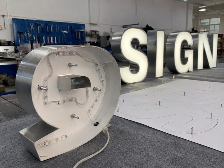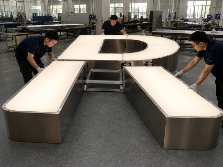

A channel-letter sign that flickers at night can look like a simple LED problem, but experienced sign technicians rarely start by replacing LEDs at random. The visible flash is only the symptom. Behind each illuminated letter is a small electrical system that can include LED modules, low-voltage wiring, connectors, one or more power supplies, controllers, wire exits, weather-protection details, and the building-side electrical connection. If any part of that path becomes unstable, the light can pulse, dim, restart, or flicker even when the LEDs themselves are still usable.
Channel letters usually flicker because stable electrical power is being interrupted somewhere between the incoming supply and the LED modules. Common causes include an overloaded or deteriorating power supply, voltage drop, loose or corroded connections, local LED-module damage, controller problems, moisture intrusion, and heat-related instability. The flicker pattern often reveals which part of the system should be inspected first.
Consider a storefront that operates normally when it switches on at 6:00 p.m., starts flickering around 8:30 p.m., and appears normal again the next morning. Replacing the first LED module you can reach may achieve nothing. The better question is what changed during those two and a half hours. Once the fault is treated as evidence rather than an annoyance, the sign begins to tell you where the problem may actually be.
What Causes Channel Letters to Flicker?

Channel letters normally flicker when power reaching the LEDs becomes unstable or a component intermittently interrupts the circuit. The fault may come from the power supply, voltage loss, wiring, connectors, LED modules, dimmers, controllers, moisture, or heat. Because several different failures create a similar visible symptom, the safest approach is to inspect the complete electrical path before deciding which component needs replacement.
Power and Voltage
The power supply is one of the first components worth checking because it converts the available electrical input into the low-voltage DC power required by the LED system. If its output becomes unstable, the connected letters may flash, pulse, dim, or repeatedly restart. A supply does not need to be completely dead to create trouble. It may still illuminate the sign while becoming unstable under sustained electrical load, elevated temperature, incorrect input conditions, or an unsuitable configuration.
Power loading should therefore be judged against the actual LEDs installed in the sign, not simply by asking whether the supply can switch them on. The module type, quantity, operating voltage, controller load, cable length, and branch arrangement all influence how the system behaves. Many channel-letter systems use low-voltage DC architectures such as 12 V or 24 V, depending on the selected LED components, but the modules, controllers, and power supplies must always be compatible with the same system design.
Voltage drop creates another common source of confusion. The basic relationship is voltage drop = current × circuit resistance. As current travels through wire, connectors, and splices, part of the available voltage can be lost. Longer runs, higher current, unsuitable conductor sizing, and high-resistance connections can increase that loss. A voltage reading taken directly at the power supply may therefore look acceptable while a distant letter receives noticeably less voltage under load.
This is especially important on long storefront names, remote-power installations, and raceway-mounted signs where several letters share electrical branches. If letters close to the supply remain stable but distant letters become dimmer or start flickering, the distribution path deserves attention before anyone begins changing modules. iduoduo treats LED layout, power matching, wiring, voltage, wire exits, waterproofing, and installation conditions as connected parts of a channel-letter project rather than isolated specifications.
Connections and Modules
Loose electrical connections often create intermittent faults that are more difficult to diagnose than a completely failed part. A weak splice, damaged cable, partially seated connector, oxidized terminal, or strained wire may conduct normally for minutes or hours and then briefly lose contact. From the street, that interruption looks exactly like an LED failure, even though the LED module receiving the unstable power may still be perfectly usable.
The location of the flicker provides useful clues. If one entire letter flashes at the same moment, the electrical feed to that letter becomes more suspicious. If only the lower portion of the letter flashes while the upper portion remains stable, a local module string, connector, or internal wire deserves closer inspection. Several neighboring letters flashing in perfect synchronization are even less likely to represent several unrelated module failures occurring simultaneously.
LED modules can still fail, of course. Heat, age, moisture exposure, damaged wiring, electrical stress, poor adhesion, or physical damage can affect an individual module or group of modules. A deteriorating LED may become intermittent before failing completely, while another failure may create a permanently dark section rather than a visible flash. The important point is that module replacement should follow diagnosis rather than replace it.
A useful field rule is that the component you can see flickering is not automatically the component that caused the flicker. Before replacing LED modules, confirm that their electrical feed is stable. Before replacing a power supply, check whether a downstream short, corroded connector, or damaged branch is repeatedly forcing that supply into protection. This simple discipline prevents a large percentage of unnecessary parts changes.
Controls and Heat
Dimmers, RGB controllers, RGBW controllers, remote-control receivers, and other control equipment add another possible failure point. If a controller is incompatible with the connected LEDs, incorrectly configured, overloaded, or beginning to fail, the lighting may pulse even when the power supply and LED modules appear normal when tested separately. When flickering occurs only during dimming, color changes, programmed effects, or remote-control operation, the control system deserves particular attention.
Heat can make these problems appear only after the sign has been operating for some time. A channel letter may switch on normally and remain stable for an hour before a power component, connector, or controller starts behaving differently as temperatures rise. That pattern does not prove thermal failure, but it gives the technician a clear reason to compare cold-start behavior with warm operating conditions rather than testing the sign for only a few minutes.
LED density also influences electrical load and internal temperature. Installing more modules is not automatically a sign of better quality. Too many modules can increase power demand and heat, while too few can create dark areas and uneven illumination. Letter depth, face diffusion, stroke width, module beam angle, power, heat, and wiring groups need to be balanced together. iduoduo’s lighting engineering process follows this system-based approach rather than using LED quantity alone as a quality indicator.
In practice, the best channel-letter system is not the one with the greatest number of components. It is the one in which the optical design, electrical design, and physical structure work comfortably together. When a sign repeatedly runs close to the operating limits of its power or thermal design, flicker may be one of the first visible warnings that something in that balance is no longer stable.
Which Flicker Pattern Points to the Fault?

Flicker location and timing can narrow the diagnosis before the sign is opened. One letter usually points toward a local module, branch, or connection problem. Several synchronized letters suggest a shared electrical source, while a whole sign flashing together moves attention farther upstream. Problems that appear only after warm-up, rain, or extended operation provide additional evidence that helps technicians prioritize testing.
One Letter
When only one letter flickers and every neighboring letter remains stable, begin with components unique to that letter. The local LED modules, branch wiring, connectors, wire exit, and any moisture affecting that specific unit are more relevant than replacing a central component that is successfully operating the rest of the sign. This is especially true when every unaffected letter remains consistently bright during the same operating period.
The geometry of the flicker matters too. Imagine a large illuminated “R.” If the complete “R” flashes together, the branch feeding the entire letter becomes an obvious area to investigate. If only the lower curved portion flashes while the vertical stroke remains stable, the problem is more likely to lie within that local circuit, connector, or module group.
Accurate reporting saves considerable service time. A message saying “the sign flickers” gives a technician very little useful information. A report saying “the lower third of the fourth letter starts flashing after approximately 90 minutes and returns to normal after the sign is switched off” provides a much better starting point. A short night video often communicates the failure pattern even more clearly.
For multi-location retail or restaurant projects, record the store, affected letter, approximate operating time, weather, repair date, and any replacement parts. That information becomes valuable when the same symptom appears elsewhere. Instead of treating every service call as a completely new event, maintenance teams can compare whether several locations are showing a similar failure mode.
Several Letters
When several letters flicker at exactly the same moment, ask what those letters share. They may use one power supply, one low-voltage branch, one controller, one raceway connection, or one section of wiring. Synchronized behavior is an important clue because several independent LED modules are much less likely to begin and stop failing in perfect unison.
Consider a twelve-letter storefront divided into three electrical groups. Letters 1-4 remain stable, letters 5-8 flicker together, and letters 9-12 remain stable. Before opening twelve individual letters, an experienced technician will normally investigate the components shared by letters 5-8. That may reduce a large sign to one branch, one connection area, or one power source requiring detailed testing.
If all twelve letters flicker at the same time, the investigation usually moves even farther upstream. The central power arrangement, main controller, switching equipment, or incoming circuit becomes more relevant than individual LED modules. This does not automatically prove a building-side problem, but it helps distinguish a system-wide interruption from several local lighting failures.
LED channel letters are physically separate units but electrically they often operate as groups. iduoduo’s engineering records treat the complete system as a combination of LEDs, power, wiring, weather protection, drainage, and installation interfaces, which makes the same system-level thinking useful when a service problem appears later.
| Flicker Pattern | First Area to Check | What the Pattern May Indicate |
| Part of one letter | Local modules, connector, internal wire | Localized electrical fault |
| One whole letter | Branch feed and local connections | Letter-specific supply issue |
| Several letters together | Shared supply or branch | Common electrical source |
| Entire sign together | Upstream power or controller | System-level interruption |
| Starts after extended use | Load and temperature | Thermal or sustained-load issue |
| Appears after rain | Wire exits, connectors, sealing | Moisture-related instability |
Timing Patterns
Intermittent flickering becomes easier to understand when the operating timeline is recorded. A fault that appears immediately after switch-on may point toward a different group of causes than one that begins only after the sign has been operating for two hours. The technician should therefore record not only whether a sign flickers, but how long it takes for the symptom to appear and what conditions are present at that time.
A practical observation schedule can be surprisingly useful. Watch the sign during the first 5 minutes, inspect it again after 30-60 minutes, and record whether anything changes after approximately 1-2 hours of continuous operation. If the fault appears only after warm-up and disappears following an overnight shutdown, temperature or sustained electrical loading deserves closer examination.
Weather can be recorded in the same way. A problem that consistently follows heavy rain is more informative than one isolated wet-weather event. Likewise, flashing that appears only during strong wind may justify checking connections or cables that can move slightly with vibration. These patterns are not final diagnoses, but they help decide which hypothesis deserves to be tested first.
The main objective is to replace guesswork with repeatable observations. Maintenance teams do not need advanced electrical equipment to provide useful first-stage evidence. Accurate videos, operating times, weather notes, and clear identification of affected letters can dramatically reduce the amount of trial-and-error work required once a qualified technician begins the electrical inspection.
How Do You Troubleshoot Flickering Channel Letters?

Effective troubleshooting moves from observation to isolation and then measurement. First identify exactly which letters flicker, when the problem appears, and which components those letters share. Next inspect accessible wiring, connectors, moisture, and visible damage. Electrical values should then be compared with the specifications of the actual LED system. Building mains, breakers, and inaccessible electrical work should be handled by qualified professionals.
Start With the Pattern
Before removing a face or opening a raceway, stand where the complete sign can be observed. The first inspection should establish four things: where the flicker appears, when it appears, how frequently it occurs, and what environmental conditions are present. Determine whether the problem affects a small module section, one complete letter, a group of letters, or the entire sign.
Watch for changes in brightness as well. A letter that gradually dims before flickering tells a different story from one that abruptly switches on and off. Record whether the behavior is rhythmic or random and whether it starts immediately or only after the system has been running. If the problem is intermittent, a short inspection during the wrong part of the operating cycle can easily produce a false conclusion.
The next step is to gather available project information. Useful records include system voltage, LED type, power-supply model, controller type, installation style, approximate age, repair history, wire exits, raceway details, and whether the sign is indoors or outdoors. Production documentation can shorten the investigation because the service technician does not have to reverse-engineer the original configuration.
A sensible troubleshooting sequence is to map the symptom, identify shared components, inspect accessible wiring, check for moisture, verify power conditions, isolate the suspect branch, repair the confirmed fault, and then retest the complete sign. This sequence may sound slower than immediately replacing a part, but in practice it often saves time because the first replacement is much more likely to be the correct one.
Check the Electrical Path
Electrical measurements become useful only when they are compared with the requirements of the installed components. A voltage reading at the power supply does not automatically prove that the same condition exists at the farthest letter. Similarly, a perfect reading taken immediately after switch-on does not explain a failure that appears only after ninety minutes of operation.
The electrical path should therefore be considered from the supply, through each splice and branch, to the LED load. Where voltage drop is suspected, measurements at more than one location can reveal whether the available voltage changes along the run under normal operating load. Where a branch fault is suspected, compare the affected branch with an unaffected branch under similar conditions.
Power calculations should use the actual module specifications and module quantity. The correct question is not whether the supply has enough nameplate wattage to light the sign briefly, but whether the supply, LEDs, controller, wiring, and installation can operate together within their intended conditions over normal daily use.
| Checkpoint | Useful Comparison | Possible Meaning |
| Power-supply output | Actual output vs. system specification | Incorrect or unstable supply |
| Near and far letters | Voltage under the same load | Distribution loss or resistance |
| Affected and stable branches | Behavior under identical conditions | Branch-specific problem |
| Cold and warm operation | Readings before and after flicker | Temperature-related instability |
| Connectors and splices | Stable vs. intermittent contact | Loose or corroded connection |
| Control system | Controlled vs. isolated operation | Dimmer or controller issue |
Electrical testing should be carried out by personnel who understand the installed system. Although the LED modules themselves are normally low-voltage components, their power supplies connect to building electrical services. The presence of low-voltage LEDs does not make breakers, mains wiring, wet electrical equipment, or high-level exterior installations suitable for untrained maintenance work.
Know When to Escalate
Store staff and facility teams can contribute valuable evidence without opening electrical equipment. They can photograph the installation, record a night video, identify the exact affected letters, note how long the sign operates before the problem appears, and record whether rain, heat, or wind changes the behavior. A photograph of an accessible power-supply label or controller label can also help the service team identify the original configuration.
The boundary changes when the problem involves mains wiring, repeated breaker trips, exposed conductors, visible overheating, burning smells, significant water around electrical equipment, or access at height. Those conditions should be handled by appropriately qualified electrical or sign-service professionals. A flickering sign is usually an operational problem, but electrical warning signs should not be ignored simply because some LEDs remain illuminated.
Manufacturer involvement can also be useful when the original production records are still available. LED type, power arrangement, drawing revisions, controllers, mounting details, and earlier QC information may help determine what replacement components are compatible and whether the same issue has appeared on a previous order.
iduoduo’s documented after-sales assessment considers LEDs, power supplies, wiring, controllers, voltage, installation, water ingress, operating environment, transportation, and physical damage rather than assuming every complaint has one standard cause. This evidence-based approach is especially important because two signs showing almost identical flickering can still require completely different repairs.
Are Weather Conditions Causing the Flicker?

Weather can contribute to channel-letter flicker when moisture, condensation, corrosion, temperature changes, or repeated outdoor exposure affect electrical components. Rain does not automatically prove a product defect; technicians need to identify where moisture entered, whether drainage remains effective, and whether connectors, wire exits, raceways, seals, and mounting penetrations are still protecting the electrical system after installation.
Rain and Moisture
If a channel-letter sign works normally in dry conditions but develops intermittent flicker during or after rain, moisture should move much higher on the investigation list. Water can enter through damaged faces, deteriorated sealing, wire exits, cable entries, mounting penetrations, raceway joints, or service openings. In some installations, the product remains visually intact from the street while moisture is reaching electrical components hidden behind the letter.
The timing can provide useful clues. A problem appearing immediately during rain may differ from one that begins several hours afterward. Water may enter one location and migrate gradually, or condensation may build as temperatures change. This is one reason simply adding sealant to the most visible seam does not always solve an intermittent outdoor fault.
Outdoor protection also requires both resistance to water entry and sensible moisture management. A channel letter is not necessarily improved by sealing every possible opening without considering drainage. Water or condensation that gets inside needs an appropriate way to leave rather than collecting around electrical connections.
iduoduo’s channel-letter engineering framework includes both weather protection and drainage within the complete product structure. For recurring service problems, compare which letter fails after each weather event, where its cable exits the wall, how it is mounted, and whether water could be reaching a connector or low point in the wiring path.
Corrosion and Drainage
Direct water entry can create an obvious failure, but corrosion often develops more slowly. A connector may continue conducting while oxidation gradually increases its electrical resistance. The sign can therefore appear normal for a long period before the connection becomes unstable enough to create intermittent flicker, dimming, or heat at the affected point.
Repeated wet-dry cycles deserve particular attention. Moisture enters, partially evaporates, returns during another weather event, and gradually affects connectors, terminals, splices, or conductive surfaces. Humid and coastal environments can accelerate these processes, but the same basic issue can occur on any outdoor installation where water remains trapped.
Drainage is therefore part of electrical reliability rather than a separate cosmetic concern. If an intended drainage path becomes blocked by dirt, paint, sealant, or later maintenance work, condensation and incidental water may stay inside the structure much longer than expected. A repair that closes every visible opening can sometimes make the long-term moisture problem worse.
Commercial signs should be maintained as complete installations rather than just illuminated faces. iduoduo’s maintenance documentation includes checking sealing, drainage, wiring, power supplies, LED modules, and controllers over the service life of an illuminated product. This is especially useful for exterior storefront signs that operate every evening and experience thousands of outdoor temperature and humidity cycles over several years.
Heat and Weather Cycles
Outdoor channel letters can experience operating conditions very different from the surrounding air. Direct sun can heat dark metal returns during the day, while LED modules and power electronics create additional heat during operation. After sunset, the enclosure may cool rapidly. Rain, wind, and seasonal temperature changes add further cycles of expansion and contraction to metals, acrylics, sealants, wiring, and connectors.
A sign that begins flickering only after extended operation should therefore be checked for a relationship between temperature and the failure. If the problem consistently appears after approximately the same operating period and disappears after cooling, thermal behavior becomes useful evidence. That does not prove a particular component is faulty, but it tells the technician that a five-minute cold-start test is unlikely to reproduce the real operating condition.
The original optical design can influence this risk. Excessive LED density raises power demand and may increase internal heat, while insufficient density can produce dark areas. Module spacing, letter depth, face material, power, and heat should be balanced rather than optimized independently. iduoduo’s lighting engineering records connect LED arrangement with geometry, diffuser material, light output, control functions, and system stability.
This becomes particularly important for storefronts, restaurants, hotels, and entertainment locations where signs may operate for many consecutive evening hours. Stable performance depends not only on whether the product lights correctly in the factory, but also on whether its electrical and mechanical design remains comfortable under the conditions it will repeatedly experience after installation.
How Can Flicker Be Prevented Before Shipping?

Flicker prevention starts during product engineering and continues through production and testing. LED layout, power loading, wiring groups, controllers, wire exits, weather protection, and service access should be planned as one system. A brief power-on check can confirm that a sign illuminates, but sustained operation is much more useful for finding intermittent wiring, controller, temperature, and power-supply problems before packing.
Load and Wiring Design
Power-supply selection should begin with the actual LED configuration rather than the overall physical size of the sign. Two logos that are both 1,000 mm wide can have very different electrical requirements because their stroke widths, letter depths, module quantities, illumination styles, face materials, and control functions may be completely different.
The engineering process should identify the selected LED module, approximate module quantity, total connected load, number of electrical groups, intended supply positions, expected wire runs, controller requirements, system voltage, and installation environment. For large signs, splitting the lighting into logical electrical branches can improve serviceability and make future fault isolation easier.
Wire routing should be planned at the same time. Long runs, unnecessary connections, poorly located junctions, and difficult-to-access power supplies create problems that are expensive to correct after the sign reaches the building. Raceway-mounted, backboard-mounted, and individually mounted systems may therefore require different electrical arrangements even when the visible lettering looks similar.
For professional projects, iduoduo’s required channel-letter information includes lighting method, LED color or CCT, voltage, power-supply requirements, mounting method, wire exit, raceway or backboard requirements, indoor or outdoor use, certification needs, and destination. Confirming those conditions before production reduces the number of electrical decisions that must otherwise be made from assumptions.
Outdoor Details
Outdoor electrical protection should be planned together with the physical structure. Wire exits, cable entries, connectors, mounting penetrations, drainage, service openings, and power-supply positions all influence long-term reliability. If those details are considered only after the metal letters have been manufactured, the final system may be harder to seal, harder to service, and more vulnerable to recurring moisture problems.
Serviceability matters as well. A power supply that technically fits behind a decorative panel may be difficult to replace after installation. Clear electrical grouping, accessible components, identifiable wires, removable sections, and documented connection logic can reduce future labor significantly. For a high-mounted storefront sign, saving one unnecessary service visit may be more valuable than saving a small amount of material during initial manufacture.
Repeat projects benefit even more from documentation. Production records can preserve LED models, module spacing, letter depth, power information, control equipment, installation details, test photographs, and illuminated videos. iduoduo’s project records can include these items for repeat-production and technical comparison.
Good records do not prevent every fault, but they make future maintenance far more efficient. If a power supply fails several years later, the service team can start with the original configuration instead of guessing which LED voltage, power capacity, controller, or mounting arrangement was used on that particular version of the sign.
72-Hour Verification
A sign that illuminates correctly for five minutes has passed a functional check, but that does not prove it will remain stable during long nightly operating periods. Intermittent connections, power-supply instability, controller faults, and abnormal temperature rise may require extended operation before they become visible. Sustained testing is therefore most valuable when it is combined with defined inspection points rather than treated as a simple countdown.
iduoduo’s documented process applies 100% lighting inspection followed by 72-hour pre-shipment testing to illuminated products. The inspection covers LED stability, power-supply stability, controllers, flicker, early failure, color variation, local dark areas, abnormal temperature rise, and wiring connections. When a problem is found, the affected component or connection is repaired or replaced and then verified again before product release.
| Pre-Shipment Check | What Is Observed | Main Risk Addressed |
| 100% lighting inspection | Every illuminated product | Dead or visibly unstable areas |
| LED stability | Module operation over time | Early module failure |
| Power stability | Supply behavior under load | Intermittent power problems |
| Controller function | Dimming or RGB/RGBW operation | Control-related flicker |
| Wiring inspection | Connections and routing | Loose electrical contact |
| Temperature observation | Operating components | Abnormal heating |
| 72-hour operation | Complete illuminated system | Intermittent early-life faults |
| Re-verification | Repaired components | Confirms correction before release |
The important point is not the number 72 by itself. The value comes from extended operation combined with specific observations and corrective action. A long test that nobody checks tells less than a controlled test in which lighting behavior, power, wiring, controllers, and temperature are actively reviewed and any abnormal result is corrected before the product leaves the factory.
When Is Repair or Replacement Needed?

A flickering channel letter does not automatically require a complete new sign. Isolated module, connector, wiring, or power-supply faults can often be repaired when the remaining system is healthy and compatible components are available. Replacement becomes more reasonable when failures are widespread, corrosion is extensive, components are heavily aged, matching replacement LEDs are unavailable, or repeated repairs no longer solve the underlying system condition.
Repair the Fault
When the cause is clearly localized, component-level repair normally makes more sense than rebuilding a complete channel-letter set. One damaged module group may need replacement, a weak splice may need to be remade, or an unstable power supply may need a compatible substitute while the letters, faces, returns, and remaining lighting continue in service.
The important word is clearly. The technician should confirm that the failure is local before replacing the visible component. Installing new LEDs will not solve unstable power coming from a shared supply, while replacing a power supply will not solve a corroded connector downstream. The repair should address the confirmed cause rather than whichever component is easiest to order.
Component compatibility also matters. Replacement LEDs should be evaluated for voltage, electrical characteristics, physical size, brightness, color, and installation method. On older signs, new modules may appear noticeably brighter than aged modules even when both technically operate correctly. That visual difference can matter on premium retail façades where a single brighter letter may look almost as undesirable as a flickering one.
Products designed with service access are much easier to repair. Removable faces, accessible wiring, logical power grouping, identifiable connections, and known power-supply locations reduce field labor. iduoduo’s maintenance documentation notes that products without practical access or clear electrical locations become more difficult and expensive to service later.
Replace When Age Spreads
Complete or partial system replacement becomes more sensible when the problem is no longer isolated. An older channel-letter set may have one flickering letter today, another failing power supply several months later, and increasing brightness differences between old and new LED modules after repeated repairs. At some point, fixing individual symptoms stops being the most economical strategy.
The decision should look beyond the price of one replacement component. Access equipment, labor, road or pedestrian control, high-level installation work, business disruption, travel, and repeated diagnostic visits can make a small electrical repair expensive. If several components of similar age are already deteriorating, one planned lighting refresh may cost less than multiple emergency service calls spread across the next year.
Visual consistency can also justify broader replacement. New LEDs installed beside heavily aged modules may differ in brightness or color. That difference may be acceptable on a utility building, but it can be difficult to accept on a luxury retail storefront or chain brand where night-time appearance must remain consistent across every letter.
Widespread corrosion, brittle wiring, repeated water intrusion, unavailable component models, several unstable power supplies, and repeated unrelated service calls all strengthen the case for broader replacement. One failed component does not prove the whole system is finished, but several independent warning signs together usually deserve a more strategic maintenance decision.
Build a Useful Service Record
Long-term maintenance becomes much easier when each service event creates a record that can be compared with the original manufacturing information and earlier repairs. A useful record includes the project number, product or letter identifier, failure date, photographs, night video, problem description, confirmed cause, replacement parts, shipping information, repair date, and follow-up result.
The original project information is equally valuable. Drawings, BOM information, LED specifications, power supplies, color information, mounting details, tests, packaging, shipping, and earlier service records can help a technician understand what was originally installed. iduoduo normally retains relevant order records for approximately 2-3 years, and documented after-sales records may include the fault date, photographs, video, cause, corrective action, parts, and follow-up improvement.
For supported projects, the documented service process targets an initial response within 24 hours after clear photographs or videos are received, a preliminary cause assessment within 24-48 hours, small replacement-part arrangements within 3-7 days, and a proposed solution for major issues within 48-72 hours. The unified quality framework is 72-Hour Pre-Shipment Testing + 3-Year Warranty.
A good service record does more than close one complaint. If a similar fault appears at another store, engineering and QC teams can compare components, production records, operating conditions, and installation details. That makes it possible to correct a recurring cause before the same problem reaches another production batch.
A flickering channel letter is ultimately a message from the electrical system. One flashing section may point to a local connector or LED module. Four letters changing at exactly the same moment may point toward a shared power branch. A sign that becomes unstable after rain may be telling you to inspect a hidden connection rather than the illuminated face. The faster the visible symptom is converted into structured evidence, the less time is spent replacing parts that were never responsible for the problem.
For new channel-letter projects, the same lesson works in reverse. Reliable lighting comes from coordinating LEDs, power supplies, wiring, controllers, letter depth, weather protection, drainage, installation interfaces, and testing before the product reaches the storefront. When those details are engineered and documented as one system, troubleshooting becomes easier, repeat production becomes more consistent, and long-term maintenance becomes far more predictable.
Frequently Asked Questions
What causes LED channel letters to flicker?
LED channel letters can flicker because of unstable power supplies, excessive voltage drop, loose electrical connections, damaged LED modules, controller problems, corrosion, moisture, or heat-related instability. The visible LED is not always the failed component. If several letters flicker together, a shared power or wiring problem becomes more likely, while one small section flickering usually points toward a more localized electrical fault.
Can a bad power supply cause channel letters to flicker?
Yes. A failing or incorrectly configured power supply can produce unstable output even when it still provides enough power to illuminate the sign. Flickering may appear immediately or only after extended operation as the power supply warms. Technicians should compare the actual connected LED load, required voltage, operating behavior, and power-supply specification before replacing the unit, because downstream wiring faults can sometimes create similar symptoms.
Can voltage drop make an LED sign flicker?
Voltage drop can contribute to dimming, unstable brightness, and flickering when resistance in long wire runs, connectors, splices, or undersized conductors reduces the voltage reaching distant LEDs. Measuring only at the power supply may miss the problem. When voltage drop is suspected, qualified technicians normally compare electrical conditions at the source and farther along the circuit while the sign is operating under its normal load.
Can rain cause channel letters to flicker?
Rain can trigger flickering when moisture reaches connectors, wiring, controllers, power components, or damaged electrical interfaces. The problem may appear during rain or several hours later as moisture migrates through the structure. Recurring wet-weather problems should be investigated around wire exits, mounting penetrations, raceways, seals, connectors, and drainage paths rather than assuming the illuminated face itself is the only possible entry point.
Why is only one channel letter flickering?
If only one letter flickers while the rest of the sign remains stable, the fault is often localized to that letter’s branch wiring, connectors, LED modules, wire exit, or moisture exposure. The exact pattern is useful. An entire letter flashing together suggests a different investigation from one small section flickering. Recording a night video helps technicians determine whether the failure is local, intermittent, synchronized, or related to operating time.
Should flickering channel letters be repaired or replaced?
Repair is usually practical when testing identifies one localized failure and the remaining LEDs, wiring, structure, and power system are still in good condition. Broader replacement becomes more sensible when several components are aging, corrosion is widespread, repeated service calls continue, compatible parts are difficult to obtain, or new LEDs cannot match the existing brightness and color closely enough for the required storefront appearance.